ATA5279/ATA5279C Six-fold LF Antenna Driver IC
1 /37Pages

ATA5279/ATA5279C Six-fold LF Antenna Driver IC
1 /37Pages
Catalog excerpts

ATA5279/ATA5279C Antenna Driver for Multiple Antennas DATASHEET Features ● Six connections for series-resonant LF coil antennas ● Drives up to 1A peak current on the first three channels and up to 700mA peak on the second three, largely independent of the battery voltage ● On-off-keyed data modulation with up to 5.7Kbit/s (manchester coded) ● Sinusoidal-like output signal for superior EMC behavior ● 20 selectable steps for current regulation for field strength measurement (RSSI) ● Output driver stages are protected against electrical and thermal overload ● Very low power-down current consumption ● SPI interface for easy microcontroller bus connection ● LF data buffer to minimize microcontroller’s CPU load during a data transmission ● Small outline package: QFN48, 7mm × 7mm
Open the catalog to page 1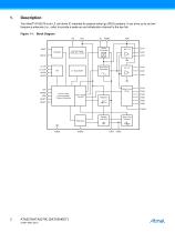
Description The Atmel® ATA5279 is an LF coil driver IC intended for passive entry/-go (PEG) systems. It can drive up to six lowfrequency-antennas (i.e., coils) to provide a wake-up and initialization channel to the key fob. Figure 1-1. Block Diagram VS OSCI Oscillator Internal Supply POR, BG, UV/OV Boost Controller Sine Wave Generator Return Line Driver Control Logic Communication Protocol Handling Driver Stage Control Zero Cross Detector
Open the catalog to page 2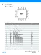
Heat Slug PGND Backside ground connection 2 RGND Reference ground 3 CINT Integration capacitor connection 4 VCC Analog 5V stabilization capacitor connection 5 VSHS Shunt resistor voltage sense input 6 VIF Digital supply voltage input 7 OSCI Oscillator input pin 8 OSCO Oscillator output pin 9 MACT Modulator active indicator output pin 10 BCNT LF-bit counter output pin 11 VSHF1 Shunt resistor driving pin 1 12 A6N1 Coil 6 negative connection line pin 1 13 A6N2 Coil 6 negative connection line pin 2 14 A3N1 Coil 3 negative connection line pin 1 15 A3N2 Coil 3 negative connection line pin 2 16 A5N1...
Open the catalog to page 3
Table 2-1. Pin Description (Continued) 24 A1N1 Coil 1 negative connection line pin 1 25 A1N2 Coil 1 negative connection line pin 2 26 A1P Coil 1 positive connection line pin 29 A4P Coil 4 positive connection line pin 30 A2P Coil 2 positive connection line pin 32 A5P Coil 5 positive connection line pin 33 A3P Coil 3 positive connection line pin 34 A6P Coil 6 positive connection line pin 36 MISO Master-ln-Slave-Out SPI output pin 37 MOSI Master-Out-Slave-In SPI input pin 39 S_CLK SPI clock input pin 40 NRES Chip reset input pin 41 IRQ Interrupt request output pin 43 PGND1 Boost converter low-side...
Open the catalog to page 4
Functional Description Operation Modes Atmel® ATA5279 features five operation modes. They are: ● Power-down mode (reset state) Idle mode Operating mode Shutdown mode Diagnosis mode Power-down mode is active after supply voltages have been applied to the chip. No internal circuitry is active in this mode and as such power consumption is minimal. If no operation of the chip is demanded, it should be kept in this state. To enter power-down mode, a negative pulse on the NRES pin for at least tNRES,min is required. After wake-up from power-down mode by a logic high signal at the S_CS pin, the chip...
Open the catalog to page 5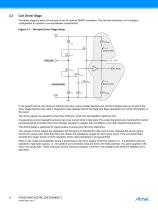
Coil Driver Stage The driver stage for each coil consists of two N-channel DMOS transistors. The low-side transistor is in Darlington configuration to maintain a source-follower characteristic. Figure 3-1. Principle Driver Stage Setup VDS Diag Enable Nmirr VSin_pre Diag Enable Internal nodes In the graphic above, the names of internal pins have a grey shaded background, and the hatched area is not part of the driver stage itself but only used in diagnostic mode (please refer to the Diagnosis Block description for further information on this topic). The driver stages are supplied by the three...
Open the catalog to page 6
Driver Stage The return line stage is built by an open drain NMOS equipped with a free wheel diode. In parallel to the diode there is a pullup resistance to terminate the inactive antenna coils. Figure 3-2. Principle Return Line Stage VDS IHSDiag 100kΩ Diag Enable VSHF Diag Enable Similar to the driver stage the components within the grey area describe the functionality in diagnosis mode. Table 3-1. States of Driver Outputs within Operation Modes Operation/ Transmission Mode Output Entering by SPI cmd Shutdown Mode Fault has detected Idle Mode Entering by S_CS Selected driver active others are...
Open the catalog to page 7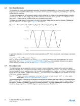
Sine Wave Generator The sinusoidal coil-driving signal is internally generated. Its amplitude is dependant on the measured coil current, and the frequency is derived from the oscillator stage. In conjunction with the output driver stages, the generated signal is optimized for low harmonic distortions. The peak-to-peak amplitude of the sinusoidal signal is directly defined by the voltage on the external integration capacitor connected to the CINT pin. This voltage, with an offset subtracted, is internally used to generate a low-voltage sine wave signal, which is in turn amplified and level-shifted...
Open the catalog to page 8
Coil Current Sensing (Zero Cross, Sample and Hold, Integrator) The coil current flows through an external shunt resistor, causing a current-dependant voltage, which is fed into the IC via the VSHS pin. By monitoring the zero crossing events of this signal, the phase of the coil current is known and hence the positive peak value can be sampled. The VSHS voltage is sampled at T/4 after the zero cross event. The peak coil current is then subtracted from an internal reference voltage that is dependant on the selected coil current, which results in the regulation difference. An amplifier stage converts...
Open the catalog to page 9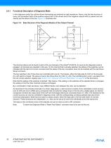
Functional Description of Diagnosis Mode In this diagnosis mode, the coil-line drivers themselves are switched to high impedance. Hence, only the test structure at every coil connection (both at the positive outputs AxP of the drivers and at the negative outputs AxN) is present and can directly test the status of the line. Figure 3-4 illustrates this: Figure 3-4. Base Structure of the Diagnosis Module of One Output Channel VDS Latch Driver x select c0, 1 bits The structure above can be found in each of the six channels of the Atmel® ATA5279. As soon as the diagnosis mode is engaged, all channels...
Open the catalog to page 10All Atmel catalogs and technical brochures
 32-bit Microcontrollers
20 Pages
 MCUs Driving Displays
12 Pages
 Touch and 3D Gesture Control
12 Pages
 16-bit MCUs and DSCs
20 Pages
 XLP PIC® MCUs
8 Pages
 8-bit MCUs
16 Pages
 AT93C56B/66B Automotive
17 Pages
 Atmel AT86RF215 Device Family
235 Pages
 AT24C01C/02C
22 Pages
 maXTouch U Series - Flyer
2 Pages


Archived catalogs
 tinyAVR ATtiny24/44/84 Preliminary
240 Pages
 ATmega164P/324P/644P Preliminary
440 Pages
 ATmega48P/88P/168P/328P Preliminary
426 Pages
 ATmega1284P Preliminary
356 Pages
 AT90PWM216/316
359 Pages
 AT90PWM2, AT90PWM3, AT90PWM2B, AT90PWM3B
361 Pages
 ATmega329/3290/649/6490 Preliminary
392 Pages
 ATmega329P/3290P Preliminary
388 Pages
 AT90CAN32/64/128
428 Pages
 AT86RF230 Preliminary
98 Pages
 ATmega48/88/168 Automotive
335 Pages
 ATtiny25, ATtiny45, ATtiny85 Automotive
192 Pages
 ATtiny24/44/84 Automotive Preliminary
225 Pages
 AT86RF231 Preliminary
180 Pages
 Biometrics (Fingerprint Sensor)
20 Pages


- Transceiver module
- Potentiometer
- Industrial converter
- Ethernet transceiver
- Analog potentiometer
- Low-noise amplifier
- Analog amplifier
- Analog converter
- Circuit board
- Operational amplifier
- 32-bit microcontroller
- Low-power microcontroller
- Analog microcontroller
- High-speed converter
- General purpose microcontroller
- DAC converter
- Communication microcontroller
- High-speed amplifier
- ARM microcontroller