

Cylindrical Worm Gear Drives

Cylindrical Worm Gear Drives
The document outlines specifications for cylindrical worm gear drives, emphasizing the importance of load factors, safety coefficients, and operating time factors. It specifies that the permissible oil sump temperature should not exceed 110°C, with a maximum temperature difference of 70°C between the oil sump and ambient temperature during continuous operation.
Load and Safety Calculations
Formulas are provided for calculating permissible worm wheel torque and required driving power at the worm shaft. The safety coefficient ranges from 1.1 to 1.4, and load factors vary based on load type and operating conditions.
Calculation Process for Worm-Gear Units
The document details the data needed to determine an AtlAntA worm-gear unit, including torque, speed, load factor, and safety factor, with a calculation example provided.
Bearing Loads and Forces
It describes the calculation of bearing forces, excluding factors like bearing friction and dynamic loads, and provides formulas for individual bearing loads.
Mounting Recommendations
Recommendations include considerations for axial play, bearing distance, and worm positioning relative to the worm gear to ensure optimal performance and self-locking capabilities.
Lubrication and Finish Treatment
Guidance is provided on lubrication, recommending synthetic gear lubricants like Klübersynth GH 6 - 220, and on the finish treatment of worm gears and shafts, emphasizing precise machining and alignment.
ATLANTA worm gears are made from hardened steel, with worm gears using high-grade special worm-gear bronze. Worms have hardened and ground flanks, and larger diameter worm gears have a grey cast iron hub. All standard drives are right-handed.
Lubrication:
Recommended synthetic gear lubricants include Klübersynth GH 6 - 220, SHELL Tivela S 220, BP Enersyn SG-XP 220, and ARAL Degol GS 220. Synthetic lubricating greases like Shell Compound A can be used for less critical applications. Mineral lubricants decrease load values by 30-40%.
Load Capacity:
ATLANTA worm-gear drives are classified by center distances for load-bearing capacity. Maximum load values are calculated for standard worm drives without cooling fans and with adequate dip-feed lubrication using synthetic gear oil. Mineral oils reduce load values by 30-40%.
Features:
Worm-gear drives are versatile, used across various industries due to multiple mounting possibilities. They feature crossed axes and a wide range of gear ratios from i = 5 to over i = 100, ensuring silent and vibration-dampened operation with high load-bearing capacity.
Catalog excerpts
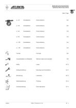
Zylinderschneckentriebe Cylindrical Worm Gear Drives Seite / Page Centre distance Centre distance Centre distance Centre distance Centre distance Selection tables and examples Mounting recommendations Kurzbe schreibung der Atlanta Produkte Centre distance Short description
Open the catalog to page 1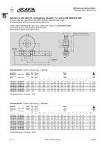
Zylinderschneckentriebe Cylindrical Worm Gear Drives Zahnform K DIN 3975/76, rechtsgangig, Qualitat 7 fs" analog DIN 3963/DIN 3967 Schneckenflanken geschliffen, aus Stahl gehartet, Wellenschafte weich, Schneckenrader aus Spezial-Schneckenradbronze Tooth profile K DIN 3975/76, right-hand, quality 7 fs“ corresp. to DIN 3963/DIN 3967 Worm flanks ground, steel hardened, shaft ends soft Worm gears of special worm-gear bronze Spann-0 fur Weiterbearbeitung JClamping dia. for finish treatment Test point Zentrierung Centres Achsabstand / Centre distance ao = 40 mm Bestell-Nr. Schnecke Schn.-Rad Order...
Open the catalog to page 2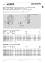
Zylinderschneckentriebe Cylindrical Worm Gear Drives Zahnform K DIN 3975/76, rechtsgangig, Qualitat 7 fs" analog DIN 3963/DIN 3967 Schneckenflanken geschliffen, aus Stahl gehartet, Wellenschafte weich, Schneckenrader aus Spezial-Schneckenradbronze, ab a = 80 mm: Nabe aus GG 20 Tooth profile K DIN 3975/76, right-hand, quality 7 fs“ corresp. to DIN 3963/DIN 3967 Worm flanks ground, steel hardened, shaft ends soft Worm gears of special worm-gear bronze, from a = 80 mm: hub of C.I. 20 Spann-0 fur Weiterbearbeitung JClamping dia. for finish treatment Test point Zentrierung Centres Achsabstand / Centre...
Open the catalog to page 3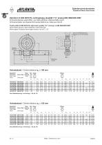
Zylinderschneckentriebe Cylindrical Worm Gear Drives Zahnform K DIN 3975/76, rechtsgangig, Qualitat 7 fs" analog DIN 3963/DIN 3967 Schneckenflanken geschliffen, aus Stahl gehartet, Wellenschafte weich, Schneckenrader aus Spezial-Schneckenradbronze, Nabe aus GG 20 Tooth profile K DIN 3975/76, right-hand, quality 7 fs“ corresp. to DIN 3963/DIN 3967 Worm flanks ground, steel hardened, shaft ends soft Worm gears of special worm-gear bronze, hub of C.I. 20 Spann-0 fur Weiterbearbeitung JClamping dia. for finish treatment Test point \Zentrierung Centres Achsabstand / Centre distance ao = 100 mm Bestell-Nr....
Open the catalog to page 4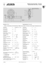
rftTLRNTfh Zylinderschneckentriebe - Formeln Cylindrical Worm Gear Drives - Formulas Schnecke / Worm Zahnezahi Number of teeth Stirnmodul Transverse module Teilkreisdurchmesser Pitch diameter Zahnezahi Number of teeth Normalmodul Normal module Eingriffswinkel Pressure angle Mittenkreisdurchmesser dm Reference diameter Reference diameter Steigungswinkel Lead angle Modul im Achsschnitt ma = Axial module Teilung in Achsrichtung ta = ma ■ n Axial pitch Steigung in Achsrichtung Ha = ta ■ z1 Axial lead Kopfkreisdurchmesser dk1 = dm1 + 2 mn Root diameter Schneckenlange Worm length Sliding speed 19100...
Open the catalog to page 5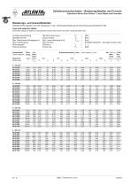
rftTLRNTfh Zylinderschneckentriebe - Belastungstabellen und Formeln Cylindrical Worm Gear Drives - Load Tables and Formulas Belastungs- und Auswahltabellen (Tabellenwerte basieren auf der Temperatur- bzw. Flankengrenzleistung bei Verwendung synthetischer Ole) Load and selection tables (The table values are based on temperature and/or flank load limits when using synthetic oils.) Nominal input power Output torque Max. torque (bending limit) Nominal ratio Efficiency Power loss Antriebs-Nennleistung Abtriebsmoment Max Drehmoment (Biegegrenze) Nenn-Ubersetzung Wirkungsprad Verlust-Leistung i = Endziffer...
Open the catalog to page 6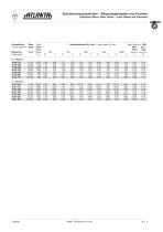
rtmRNTfb Zylinderschneckentriebe - Belastungstabellen und Formeln Cylindrical Worm Gear Drives - Load Tables and Formulas Centre distance setzg. Dreh- mom. Bestell-Nr. Ratio torque 500 Antriebsdrehzahl (n1) min-1/ Input speed (n1) rpm bei / with n1 = 1500 Wirk- Verl.- Grad Lstg. 3000 efficiency power loss
Open the catalog to page 7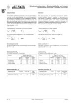
Zylinderschneckentriebe - Belastungstabellen und Formeln Cylindrical Worm Gear Drives - Load Tables and Formulas rftTLRNTfhAllgemeines Fur die Werte der Belastungstabelle wurde ein gleichmaBiger, stoBfreier Betrieb zugrunde gelegt. Da die Anwendungsfalle in der Praxis sehr verschieden sind, ist es erforderlich, diejewei-ligen Verhaltnisse durch entsprechende Faktoren S, KA und bB zu berucksichtigen (siehe nachstehend). Der Unterschied zwischen Olsumpftemperatur und Umgebungstemperatursoll bei Dauerbetrieb 70 °C nicht uberschreiten. Als Maximum fur Olsumpf gelten 110 °C. General The values given...
Open the catalog to page 8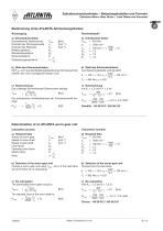
rftTLRNTfh Zylinderschneckentriebe - Belastungstabellen und Formeln Cylindrical Worm Gear Drives - Load Tables and Formulas Bestimmung eines ATLANTA-Schneckengetriebes a) Erforderliche Daten Schneckenrad-Drehmoment Drehzahl der Schneckenwelle Drehzahl der Radwelle Belastungsfaktor Betriebsdauerfaktor Sicherheitsfaktor Ubersetzungsverhaltnis b) Wahl des Schneckentriebes b) Wahl des Schneckentriebes Mit T2erf. und iaus der Belastungstabelle einen Schneckentrieb Aus Belastungstabelle wird gewahlt: wahlen, der noch nachgepruft werden muB. 1500 c) Nachrechnung Das zulassige Schneckenrad-Drehmoment...
Open the catalog to page 9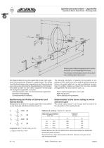
Zylinderschneckentriebe - Lagerkrafte Cylindrical Worm Gear Drives - Bearing loads Die folgende Berechnung der Lagerkrafte ist auf unser Lager-Norm-Schneckentrieb-Programm zugeschnitten. Sie erfolgt ohne Berucksichtigung der Lagerreibung, der Planschwirkung usw. sowie ohne dynamische Zusatzbelastung. Der Einfach-heit halber wurden von den vielen moglichen Anordnungen die haufigsten ausgewahlt, und zwar: Schneckenwelle unten zum Schneckenrad angeordnet. Schnecke rechtsgangig, Schneckenwelle ist treibend. Bestimmung der Krafte an Schnecke und Schneckenrad MaBgebend fur die Berechnung der Lagerkrafte...
Open the catalog to page 10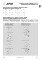
Zylinderschneckentriebe – lagerkräfte (Fortsetzung) Cylindrical Worm Gear Drives – Bearing loads (continued) Einzellagerkräfte der Schneckenwelle und der Schneckenradwelle Individual bearing loads of worm shaft and worm‑gear shaft FIu Bestimmung der Größe und der Richtung der radialen lagerkräfte Determination of the magnitude and the direction of the radial bearing forces Erklärung: Soll nur die Größe der Kräfte bestimmt werden, so genügt die Addition mit Hilfe der angegebenen algebraischen Formeln. Soll beides, Größe und Richtung der Kräfte, bestimmt werden, ist die geometrische Addition vorteilhafter....
Open the catalog to page 11All ATLANTA catalogs and technical brochures
 Straight‑tooth Bevel Gears
13 Pages
 Straight tooth system
1 Page
 helical tooth system
1 Page
 BV Hypoid Gearbox
7 Pages
 APG / APGS Planetary Gearbox
8 Pages
 Worm Gear Motors
65 Pages
 Servo Drive System
251 Pages
 Driving Elements
396 Pages
 HighForce ZTRS/ZTR/ZR
180 Pages


Archived catalogs
 Product Overview_2016
11 Pages
 Product Overview_2011
12 Pages
 TR Pinion
20 Pages
 BG-Bevel Gear Unit
24 Pages
 Planetary-Worm Gear Box
24 Pages
 Screw Jack Gearbox
10 Pages
 Precision-racks quality 4
2 Pages
 N - Worm Gear Unit
20 Pages
 High Thrust Linear Actuator
109 Pages
 Standard Worm Gear Units
44 Pages

- Actuator
- Linear actuator
- Planetary gearbox
- Electric actuator
- Precision gearhead
- Right angle gearhead
- Multi-stage gearhead
- Screw actuator
- Dual-stage gearbox
- High-performance gearhead
- Bevel gearhead
- Greasing system
- Ball screw actuator
- Screw jack
- Servo motor gearhead
- Rack and pinion
- Straight-toothed sprocket wheel
- Oil greasing system
- Servo-gearbox
- Ball screw