- Catalogs
- Atlanta Drive Systems
- Complete ATLANTA Servo Drive Systems Catalog
Complete ATLANTA Servo Drive Systems Catalog

Complete ATLANTA Servo Drive Systems Catalog
ATLANTA Drive Systems Inc. is a leader in high-quality power transmission solutions, specializing in machine tools, woodworking, robotics, and packaging machines. The company is renowned for its high-quality racks and has a global presence.
Product Specifications
The document details various servo gearbox families, including HT High-Torque, HP High-Performance, E Economy, and B Basic Gear Units. Each type offers different output torque, backlash, and stiffness levels, suitable for applications like machine tools, laser cutting, and robotics.
Order Codes and Examples
Examples of high-performance gear units and racks are provided, illustrating order codes, design specifications, and ratios.
Technical Details
Includes technical specifications for gear units, such as center distances, output shaft designs, and adjustable backlash options. It also provides selection and load tables, mounting guides, and maintenance instructions.
Key Features
- High precision and stiffness in gear units.
- Adjustable backlash options for enhanced performance.
- Comprehensive range of combinations for various applications.
Conclusion
ATLANTA Drive Systems offers a wide range of servo drive solutions, setting standards for technological leadership in the industry.
Designed for modern three-phase and DC servo-motors, these units feature low-clearance gearing, high loading values, and robust construction.
Specifications
Adjustable backlash (<1 arcmin), light metal construction for heat dissipation, robust bevel roller bearings, and compliance with DIN 3975/76 standards.
Connecting Elements
Special couplings for motor/gear units, featuring nitrided, preassembled models for motor shafts without keys.
Selection and Load Tables
Tables for selecting gear units based on driving speed, torque, and power requirements, emphasizing temperature limits during continuous full-load operation.
Mounting and Maintenance
Instructions for mounting gear units, including recommendations for positioning the worm shaft and coupling installation. Maintenance guidelines include adjusting circumferential backlash and changing lubricants.
Additional Features
Positive, torsion-free connection between gear unit and output shaft, with options for various output drive shafts and gearwheels.
Focus on E Servo-Worm Gear Units with less than 5 arcmin backlash. Includes information on dimensions, mounting, maintenance, and selection criteria.
Specifications
Center distances for gear units range from 32 mm to 100 mm, with minimal backlash for enhanced precision.
Mounting and Maintenance
Instructions for mounting surfaces, key connections, and shrink-disk connections.
Selection and Load Tables
Tables for selecting gear units based on driving speed, torque, and power requirements.
Accessories and Motor Applications
Details on couplings, shrink-disk clamping sets, and motor flanges.
Key Data from Tables
Order codes, center distances, ratios, and reduced inertia (Jred) values, aiding in gear unit selection.
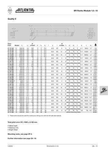
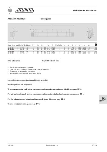
Specifications and data for rack and pinion systems, focusing on maximum permissible feed forces, material specifications, heat treatment processes, and quality standards.
Specifications
Lists various rack and pinion systems with dimensions, material compositions, and heat treatment processes.
Procedures
Guidelines for checking availability and selecting appropriate systems based on module and quality requirements.
Standards and Recommendations
Quality standards categorized by module and application type, with recommendations for heat treatment and material selection.
Data Summary
Tables present maximum feed forces for various configurations, organized by module and quality.
Key Insights
Emphasizes the importance of selecting the right material and heat treatment process for performance optimization.
Catalog excerpts

Servo-Drive System ATLANTA Drive Systems Inc. 1775 Route 34, Unit D-10 Farmingdale, NJ 07727 USA Telephone: Fax: E-Mail: Internet: Duplication – even by way of excerpts – is not allowed without our express permission. Dimensions and any other technical details given in this catalogue are subject to alterations without notice and are completely without obligation on our part. All rights to make technical changes to the dimensions and the range of our standard programme are reserved.
Open the catalog to page 1
Tradition. Innovation. Progress. ATLANTA Drive Systems has offered convincing high-quality power transmission solutions for more than 75 years. As a medium-sized company we have specialized in the development, construction and production of high quality drive systems. ATLANTA customers are found in all areas of transmission engineering. The main focus however, lies in machine tool, woodworking machines, robotics and handlings, food machinery, packaging machines, boxing machines and special purpose machines. We are market leaders in high quality racks and define market trends. All components of...
Open the catalog to page 2
Order Codes - Examples Example High-Performance Gear Units Gear Units Keyway Design Center Distance High-Performance Shrink-Disk Design Center Distance with Holes Rack Length
Open the catalog to page 4
Servo Gearboxes HT High-Torque Gear Units < 11 GA HP High-Performance Gear Units <2' GB E Servo-Worm Gear Units <5' GC B Servo-Worm Gear Units < 12' GD BG Servo-Bevel Gear Units <6' GE Gear Units Calculation and Selection GF Pinion and Output Drive Shafts GG Shrink-Disk Clamping Sets GH Mounting Guide for Servo-Gear-Boxes and Servo Motors Gl Racks and Pinions Helical Tooth System m = 1.5 - 12 ZA Straight Tooth System m = 1 - 12 ZB Integrated Racks for Guides m = 2 - 4 ZC Rack and Pinion Drive - Calculation and Selection ZD
Open the catalog to page 5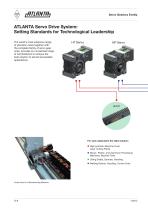
Servo Gearbox Family ATLANTA Servo Drive System: Setting Standards for Technological Leadership The world‘s most extensive range of precision racks together with the complete family of servo gear units, provides an unmatched range of combinations to achieve the best solution to almost all possible applications. For each application the right solution: n High-precision Machine Tools, Laser Cutting Plants n Wood-, Plastic- and Aluminium Processing Machines, Machine Tools n Lifting Shafts, Gantries, Handling n Welding Robots, Handling, Control Units Linear Axis of a Woodworking Machine
Open the catalog to page 6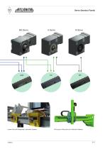
Servo Gearbox Family BG Servo E Servo B Servo Linear Axis with Integrated Lubrication System Driving and Lifting Axis of a Robotic Palletizer
Open the catalog to page 7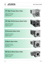
Servo Gearbox Family HT High-Torque Gear Units 150 % Output Torque Backlash < 1 arcmin Highest stiffness HP High-Performance Gear Units 100 % Output Torque Backlash < 2 arcmin Highest stiffness E Economy Gear Units 100 % Output Torque Backlash < 5 arcmin Highest stiffness B Basic Gear Units 90 % Output Torque Backlash < 12 arcmin High stiffness BG Servo-Bevel Gear Units 100 % Output Torque Backlash < 6 arcmin Highest stiffness
Open the catalog to page 8
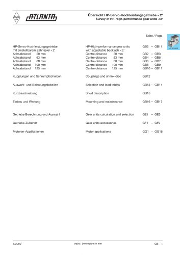
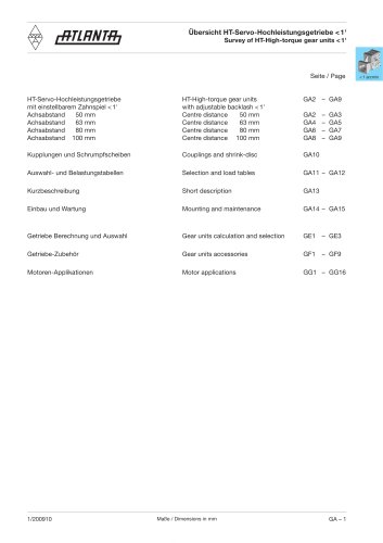
HT High-Torque Gear Units < 1' Page HT High-Torque Gear Units with Adjustable Backlash < 1' Center Distance 50 mm Center Distance 63 mm Center Distance 80 mm Center Distance 100 mm Selection and Load Tables Short Description Gear Units Calculation and Selection GF1 – GF3 Gear Units Accessories
Open the catalog to page 9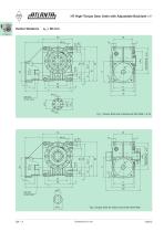
HT High-Torque Gear Units with Adjustable Backlash < 1' Center Distance Fig. 1 Output Shaft with Interface EN ISO 9409-1-A-40 Fig. 2 Output Shaft for Clamp Connection 80 84 036
Open the catalog to page 10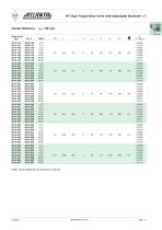
HT High-Torque Gear Units with Adjustable Backlash < 1' Center Distance Order Code Fig.1 Fig. 2 Ratio i DG7 k Other center distances and ratios on request.
Open the catalog to page 11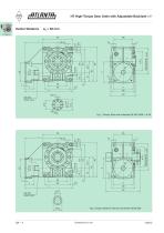
HT High-Torque Gear Units with Adjustable Backlash <1' Fig. 1 Output Shaft with Interface EN ISO 9409-1-A-50 Fig. 2 Output Shaft for Clamp Connection 80 85 050
Open the catalog to page 12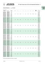
HT High-Torque Gear Units with Adjustable Backlash < 1' Center Distance Order Code Fig.1 Fig. 2 Ratio i DG7 k r Other center distances and ratios on request.
Open the catalog to page 13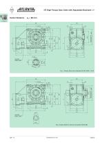
HT High-Torque Gear Units with Adjustable Backlash < 1' Center Distance Fig. 1 Output Shaft with Interface EN ISO 9409-1-A-63 Fig. 2 Output Shaft for Clamp Connection 80 86 062
Open the catalog to page 14
HT High-Torque Gear Units with Adjustable Backlash <1' Order Code T Jred Other center distances and ratios on request.
Open the catalog to page 15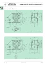
HT High-Torque Gear Units with Adjustable Backlash < 1' Center Distance Fig. 1 Output Shaft with Interface EN ISO 9409-1-A-80 Fig. 2 Output Shaft for Clamp Connection 80 87 080
Open the catalog to page 16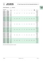
HT High-Torque Gear Units with Adjustable Backlash < 1' Center Distance Order Code Fig.1 Fig. 2 Ratio i DG7 k r Other center distances and ratios on request.
Open the catalog to page 17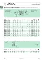
Connecting Elements Special Couplings for Motor/Gear Units, Rigid Model, nitrided, preassembled for Motor Shafts without Key < 1 arcmin Bore on gear unit side low-clearance tooth-hub profile corresponding to DIN 5480 for push-fitting Bore on motor side with locking elements as clamp connection Reference Diameter for Mounting 1) Spare part clamping element Shrink-Disk Clamping Sets for Output Drive Shafts of Gear Series 98 8. ... L1
Open the catalog to page 18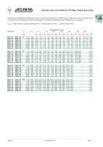
Selection and Load Tables for HT High-Torque Gear Units The values in the tables are based upon wear or maximum flank load at 12,000 hours full load and on servo-operation. With continuous full-load operation it may be necessary to consider temperature limits! (Please ask us, if in doubt.) < 1 arcmin T2max. = static torque to avoid tooth fracture, P1 = driving power in kW, T2 = output torque in Nm. Driving Speed n1 in rpm Order code a0 i T2 max. 500 750 1000 1500 3000 4000 5000 η P1 T2 P1 T2 P1 T2 P1 T2 P1 T2 P1 T2 P1 T2 at (mm) (kw) (Nm) (kw) (Nm) (kw) (Nm) (kw) (Nm) (kw) (Nm) (kw) (Nm) (kw)...
Open the catalog to page 19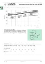
Selection and Load Tables for HT High-Torque Gear Units Gearing Efficiency of Servo-Worm Gear Units with Driving Worm and under Full Load. Additional Loads on Output Drive The data given are reference values. You should consider the values arising from the choice of the tooth system. It is assumed that the point of action of the force is the center of the shaft. In cases where additional axial forces occur, over and above high transverse forces, please ask for advice. Center Distance Dimensions Center Casing/ EN ISO Clamp EN ISO Clamp EN ISO Clamp EN ISO Clamp CenterTeeth Connect. Connect. Connect....
Open the catalog to page 20All Atlanta Drive Systems catalogs and technical brochures
 Linear Guideway
118 Pages
 Linear Rail Systems
63 Pages
 Right-Angle Bevel Gearboxes
18 Pages
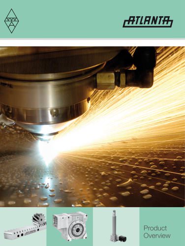 ATLANTA Product Overview
12 Pages
 ATLANTA BG Servo-Bevel Reducers
13 Pages
 ATLANTA B Servo-Worm Reducers
16 Pages
 ATLANTA E Servo-Worm Reducers
18 Pages
 ATLANTA HP Servo-Worm Reducers
17 Pages
 ATLANTA HT Servo-Worm Reducers
15 Pages
 ATLANTA Pinion Range
40 Pages
 ATLANTA Rack Range
39 Pages


- Cylinder
- Planetary gearbox
- Coaxial gearhead
- Precision gearhead
- Right angle gearhead
- Compact gearhead
- Gear train gear reducer
- Transmission gearhead
- Shaft gearhead
- Machines gearbox
- Clamp gearbox
- Bevel gearhead
- Electric motor gearhead
- Modular gearhead
- Electric cylinder
- Greasing system
- Screw jack
- Oil greasing system
- Servo motor gearhead