
- Catalogs
- Atlanta Drive Systems
- ATLANTA HT Servo-Worm Reducers

ATLANTA HT Servo-Worm Reducers
ATLANTA HT Servo-Worm Reducers
This document provides a comprehensive overview of high-torque servo gear units with adjustable backlash, focusing on various center distances and configurations. It includes specifications, dimensions, order codes, and details on couplings and connecting elements.
The gear units feature adjustable backlash of less than 1 arcminute and are available in center distances of 50 mm, 63 mm, 80 mm, and 100 mm. Detailed dimensions and configurations are provided for each distance, ensuring compatibility with EN ISO 9409-1 standard output shafts.
Each center distance includes specific order codes, gear ratios, and technical specifications such as dimensions and inertia values. The gear units are designed for compatibility with standard output shafts.
Special couplings for motor/gear units are detailed, featuring rigid, nitrided, and preassembled designs for motor shafts without keys. Specifications include dimensions, torque values, and assembly instructions.
Tables are provided to assist in selecting the appropriate gear unit based on application requirements, including load capacities and other critical parameters.
Instructions for mounting and maintaining the gear units are included, emphasizing proper installation and longevity. Procedures for adjusting circumferential backlash and changing lubricants are detailed.
Customization options for other center distances and gear ratios are available upon request.
Mounting instructions emphasize proper alignment and lubrication. Steps for installing couplings and output shafts highlight the need for clean contact surfaces and correct torque application.
Components adhere to DIN standards, such as DIN 5480 for tooth-hub profiles and DIN EN ISO 9409-1-A for gear unit interfaces. Recommendations include using the largest contact faces for mounting and ensuring even torque distribution during assembly.
Tables include order codes, dimensions, torque values, and efficiency ratings for various gear units, providing reference values for selecting and loading high-torque gear units.
Emphasis is placed on low-clearance gearing and high loading values. The importance of using annular spring elements for secure motor connections and the availability of various output drive shafts for different applications is highlighted.
Ensure even gaps between coupling and contact face, and perform a final check of true running. Insert the motor with the coupling into the gear centering piece and secure it to the gearbox.
If not pre-mounted, clean the pinion and gearbox interface, mount the pinion, and tighten screws crosswise to the specified torque.
Slide the shrink disc onto the hollow shaft extension, insert the output shaft fully, and tighten clamping screws evenly to the specified torque.
Various torque values are provided for different order codes and thread holes to ensure proper assembly and maintenance.
Backlash adjustment and lubricant change procedures are detailed, with recommendations for synthetic lubricants and regular checks.
Klübersynth GH 6 - 220, SHELL Tivela S 220, BP Energol SG-XP 220, ARAL Degol GS 220.
IP65/67 according to DIN 40 050, with separate verification for corrosion protection.
Oil quantities are specified based on the center distance of the gear unit.
Catalog excerpts

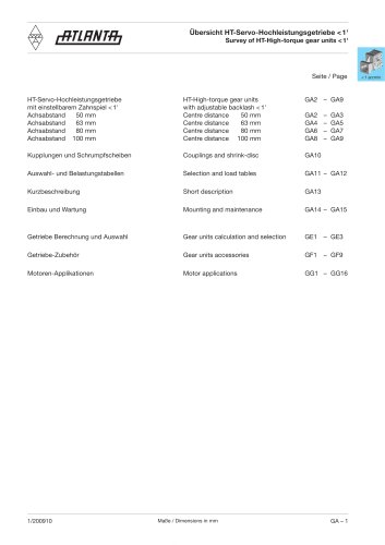
1/200910 Maße / Dimensions in mm GA – 1 < 1 arcmin Übersicht HT-Servo-Hochleistungsgetriebe < 1' Survey of HT-High-torque gear units < 1' Seite / Page HT-Servo-Hochleistungsgetriebe HT-High-torque gear units GA2 – GA9 mit einstellbarem Zahnspiel < 1' with adjustable backlash < 1' Achsabstand 50 mm Centre distance 50 mm GA2 – GA3 Achsabstand 63 mm Centre distance 63 mm GA4 – GA5 Achsabstand 80 mm Centre distance 80 mm GA6 – GA7 Achsabstand 100 mm Centre distance 100 mm GA8 – GA9 Kupplungen und Schrumpfscheiben Couplings and shrink-disc GA10 Auswahl- und Belastungstabellen Selection and load tables GA11 – GA12 Kurzbeschreibung Short description GA13 Einbau und Wartung Mounting and maintenance GA14 – GA15 Getriebe Berechnung und Auswahl Gear units calculation and selection GE1 – GE3 Getriebe-Zubehör Gear units accessories GF1 – GF9 Motoren-Applikationen Motor applications GG1 – GG16
Open the catalog to page 1
GA – 2 Maße / Dimensions in mm 1/2005 < 1 arcmin Achsabstand / Centre distance ao = 50 mm HT-Servo-Hochleistungsgetriebe mit einstellbarem Zahnspiel < 1' HT-High-torque gear units with adjustable backlash < 1' Bild 1 Abtriebswelle mit Schnittstelle analog EN ISO 9409-1-A-40 Fig. 1 Output shaft with interface according analog EN ISO 9409-1-A-40 Bild 2 Abtriebswelle für Klemmverbindung 80 84 036 Fig. 2 Output shaft for clamp connection 80 84 036 M 6 x 12
Open the catalog to page 2
GA – 4 Maße / Dimensions in mm 1/2009 < 1 arcmin HT-Servo-Hochleistungsgetriebe mit einstellbarem Zahnspiel < 1' HT-High-torque gear units with adjustable backlash < 1' Achsabstand / Centre distance ao = 63 mm Bild 2 Abtriebswelle für Klemmverbindung 80 85 050 Fig. 2 Output shaft for clamp connection 80 85 050 Bild 1 Abtriebswelle mit Schnittstelle analog EN ISO 9409-1-A-50 Fig. 1 Output shaft with interface according analog EN ISO 9409-1-A-50 M 6 x 12
Open the catalog to page 4
GA – 6 Maße / Dimensions in mm 1/2009 < 1 arcmin HT-Servo-Hochleistungsgetriebe mit einstellbarem Zahnspiel < 1' HT-High-torque gear units with adjustable backlash < 1' Achsabstand / Centre distance ao = 80 mm Bild 1 Abtriebswelle mit Schnittstelle analog EN ISO 9409-1-A-63 Fig. 1 Output shaft with interface according analog EN ISO 9409-1-A-63 Bild 2 Abtriebswelle für Klemmverbindung 80 86 062 Fig. 2 Output shaft for clamp connection 80 86 062
Open the catalog to page 6
GA – 8 Maße / Dimensions in mm 1/2005 < 1 arcmin HT-Servo-Hochleistungsgetriebe mit einstellbarem Zahnspiel < 1' HT-High-torque gear units with adjustable backlash < 1' Achsabstand / Centre distance ao = 100 mm Bild 1 Abtriebswelle mit Schnittstelle analog EN ISO 9409-1-A-80 Fig. 1 Output shaft with interface according analog EN ISO 9409-1-A-80 Bild 2 Abtriebswelle für Klemmverbindung 80 87 080 Fig. 2 Output shaft for clamp connection 80 87 080 M 8 x 16
Open the catalog to page 8
GA – 12 Maße / Dimensions in mm 1/2009 < 1 arcmin Auswahl- und Belastungstabellen für HT-Servo-Hochleistungsgetriebe Selection and load tables for HT-high-torque gear units Verzahnungswirkungsgrad für Servo-Schneckengetriebe bei treibender Schnecke und unter Volllast. Gearing efficiency of servo worm gear units with driving worm and under full load. Wirkungsgrad / efficiency ç % Zusatzbelastungen Abtrieb Die Angaben sind Richtwerte. Aus der Verzahnung sich ergebende Werte sind zu berücksichtigen. Der Kraftangriff wurde auf Mitte Wellenzapfen angenommen. Treten neben hohen Radialkräften gleichzeitig...
Open the catalog to page 12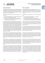
1/2005 Maße / Dimensions in mm GA – 13 < 1 arcmin HT-Servo-Hochleistungsgetriebe HT-High-torque gear units Kurzbeschreibung ATLANTA-HT-Servo-Hochleistungs-Schneckengetriebe sind speziell zum Einsatz mit Dreh- und Gleichstrom-Servomotoren der neuen Generation entwickelt worden. Sie sind, ebenso wie alle anderen Artikel dieses Kataloges, in der Regel ab Lager bzw. kurzfristig lieferbar. Folgende Merkmale zeichnen unsere HT-Hochleistungs-Getriebe aus: • spielarme Verzahnung (Spiel < 1') mit Nachstellmöglichkeit • bis zu 150 % höhere Belastungswerte • Gehäuse aus Leichtmetall für optimale Wärmeabfuhr...
Open the catalog to page 13
GA – 14 Maße / Dimensions in mm 1/2007 < 1 arcmin Einbau und Wartung HT-Servo-Hochleistungsgetriebe Mounting and maintenance HT-high-torque gear units Montageanleitung Schneckengetriebe Es stehen 5 bearbeitete Anbauflächen mit ausreichend dimensionierten Befestigung- und Gewindebohrungen für eine verspannungsfreie Montage in allen Einbaulagen zur Verfügung. Bei voller Ausnutzung der Zusatzkräfte (s. Seite GA-12) empfehlen wir die Montage an den größten Anlageflächen, d.h. an einer der beiden Deckelseiten vorzunehmen. Die günstigste Einbaulage für die Schmierung wird bei seitlicher bzw. untenliegender...
Open the catalog to page 14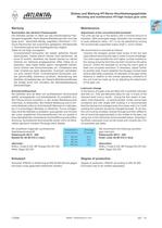
1/2009 Maße / Dimensions in mm GA – 15 < 1 arcmin Wartung Nachstellen des Verdreh-Flankenspiels Die Getriebe werden im Werk auf das kleinstmögliche Flankenspiel eingestellt. Nach längerer Betriebszeit kann sich das Spiel durch Verschleiß-Abtrag vergrößern (Richtwert >15’). Durch Nachrücken der exzentrisch gelagerten Abtriebswelle (= Schneckenrad) ist eine Spielregulierung möglich. Dabei ist wie folgt vorzugehen: Innensechskant-Schrauben der beiden seitlichen Deckel abschrauben, hierbei jedoch Deckel nicht abnehmen, da sonst Öl austritt. Verdrehen der beiden Deckel zur nächst höheren am Gehäuse...
Open the catalog to page 15All Atlanta Drive Systems catalogs and technical brochures
 Linear Guideway
118 Pages
 Linear Rail Systems
63 Pages
 Right-Angle Bevel Gearboxes
18 Pages
 ATLANTA Product Overview
12 Pages
 ATLANTA BG Servo-Bevel Reducers
13 Pages
 ATLANTA B Servo-Worm Reducers
16 Pages
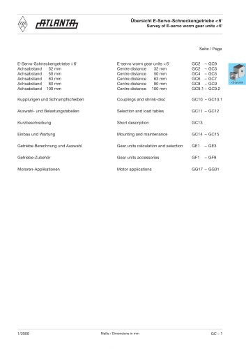 ATLANTA E Servo-Worm Reducers
18 Pages
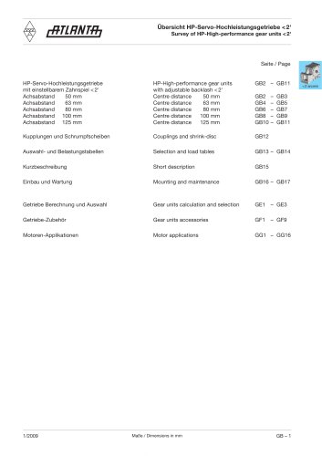 ATLANTA HP Servo-Worm Reducers
17 Pages
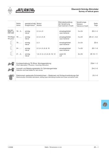 ATLANTA Pinion Range
40 Pages
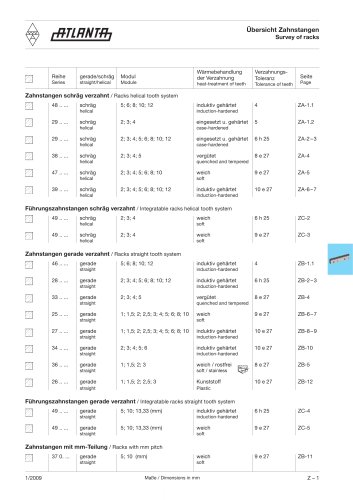 ATLANTA Rack Range
39 Pages



- Cylinder
- Planetary gearbox
- Coaxial gearhead
- Precision gearhead
- Right angle gearhead
- Compact gearhead
- Gear train gear reducer
- Transmission gearhead
- Shaft gearhead
- Machines gearbox
- Clamp gearbox
- Electric motor gearhead
- Bevel gearhead
- Modular gearhead
- Electric cylinder
- Greasing system
- Screw jack
- Servo motor gearhead
- Rack and pinion
- Straight-toothed sprocket wheel