- Catalogs
- ATESTEO GmbH & Co. KG
- Manual VECTO
Manual VECTO
1 /26Pages

Manual VECTO
1 /26Pages
Catalog excerpts

VECTO VECTO is a tool that allows you to open multiple VETAS at the same time to configure and read it. It makes it easier to handle the device and provides greater clarity than the usual terminal. A ATESTEO Excellence in drivetrain testing
Open the catalog to page 1
VECTO installation
Open the catalog to page 4
VECTO installation To start the installation execute the „VECTO_SETUP_XXXX.exe
Open the catalog to page 5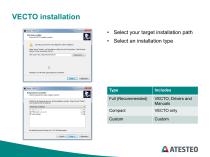
• Select your target installation path• Select an installation type Type Full (Recommended) VECTO, Drivers and Manuals VECTO only Custom
Open the catalog to page 6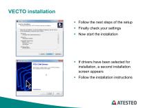
■ Follow the next steps of the setup ■ Finally check your settings ■ If drivers have been selected for installation, a second installation screen appears ■ Follow the installation instructions
Open the catalog to page 7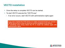
■ Once the setup is complete VECTO can be started ■ To start VECTO execute the “VECTO.exe” • If an error occurs, start VECTO with administrative rights again If you have installed the FTDI drivers it is highly recommend that you connect a VETAS device first in order to check the correct installation of the drivers. If something went wrong reboot the PC or install the software again with administrative rights.
Open the catalog to page 8
Device selection
Open the catalog to page 9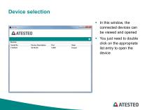
Device selection In this window, the connected devices can be viewed and opened You just need to double click on the appropriate list entry to open the devic
Open the catalog to page 10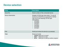
Serial port where the device is connected Device Description Detailed VETAS type description. To use all functions of VECtO be sure that the VETAS has one of the following VETAS type descriptions: Serial port state: ■ Closed: Serial port is closed ■ Open: Serial port is open ■ Error: Serial port is used by another program
Open the catalog to page 11
Control screen
Open the catalog to page 12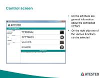
On the left there are general information about the connected VETAS On the right side one of the various functions can be selected
Open the catalog to page 13
Values screen
Open the catalog to page 14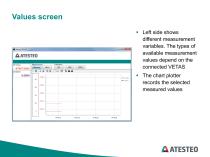
Left side shows different measurement variables. The types of available measurement values depend on the connected VETAS The chart plotter records the selected measured values
Open the catalog to page 15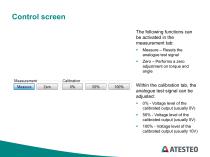
The following functions can be activated in the measurement tab: ■ Measure - Resets the analogue test signal ■ Zero - Performs a zero adjustment on torque and angle Within the calibration tab, the analogue test signal can be adjusted: ■ 0% - Voltage level of the calibrated output (usually 0V) ■ 50% - Voltage level of the calibrated output (usually 5V) ■ 100% - Voltage level of the calibrated output (usually 10V)
Open the catalog to page 16
VETAS settings
Open the catalog to page 17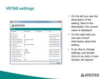
■ On the left you see the description of the setting. Next to the description, the current value is displayed ■ On the right side you can see a short information about the setting ■ If you like to change settings, just double click on an entry. A new window will appear
Open the catalog to page 18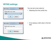
You can set a new value by ■ Selecting from the combo box Or by typing a valid value in the text field
Open the catalog to page 19
■ After the new value has been set, the check box in the left side of the window will be checked. That means that this value is changed when you click on “Apply” ■ If you do not want set the new value, just uncheck the check box
Open the catalog to page 20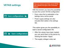
Data can only be read if the saved VETAS type matches the type of the connected device. 0 Save configurations & With this function you have the possibility to save the current VETAS configuration ■ Every value that is selectable in the settings menu will be saved ■ Power supply settings are also included (Not visible in the settings list) □ b Open configurations This option gives you the possibility to load a saved configuration file ■ After the values have been loaded, you can send them to the device by clicking the button “Apply” ■ The supply voltage is also set
Open the catalog to page 21
Power settings
Open the catalog to page 22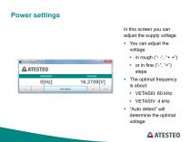
In this screen you can adjust the supply voltage ■ The optimal frequency is about: ■ “Auto detect” will determine the optimal voltage
Open the catalog to page 23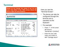
Terminal Please do not change any values if you do not know what effect it has. With wrong values the device might not work properly! Here you see the “Terminal-Screen” The device can also be configured through the terminal and is operated via the keyboard For example: Press “1” the cursor will jump to “Sensitivity1+ [Hz/Nm]” Enter the new valid value und confirm it wit
Open the catalog to page 25
All ATESTEO GmbH & Co. KG catalogs and technical brochures
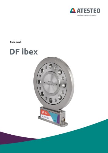
 Data sheet DF4 ibex
21 Pages
 Data sheet DF5 ibex
21 Pages
 Data sheet F4xS
21 Pages
 Data sheet DF5 dual
23 Pages
 Data sheet DF4 dual
23 Pages
 Data sheet DF3 dual
23 Pages
 Data sheet DF2 dual
23 Pages
 Data sheet DF1 dual
23 Pages
 Manual CapSync HVT
68 Pages
 Data sheet CapSync HVT
7 Pages
 Manual IRTS series
116 Pages
 Data sheet IRTS-P
11 Pages
 Manual VETAS 3
30 Pages
 Manual steering wheel
17 Pages
 Data sheet steering wheel
9 Pages
 Manual DST series
69 Pages
 Data sheet DST series
13 Pages
 Data sheet TiS Z50
20 Pages
 Manual T series
124 Pages
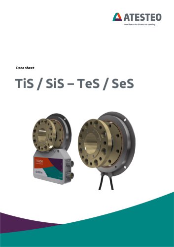 Data sheet TeS Z50
21 Pages
 Manual RT11 series
124 Pages
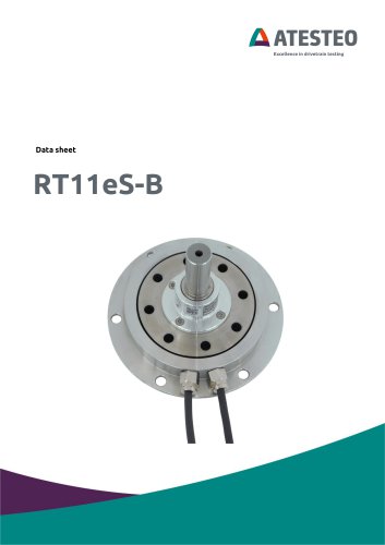 Data sheet RT11eS-B
20 Pages
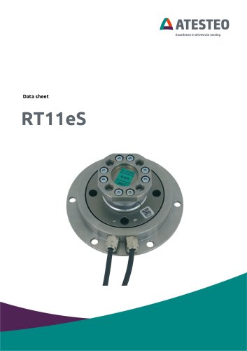 Data sheet RT11eS
17 Pages
 Manual HSTTeS series
124 Pages
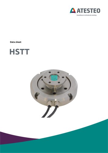 Data sheet HSTTeS series
20 Pages
 Data sheet F23 RTS
7 Pages
 Data sheet F3 RTS
7 Pages
 Data sheet F5xS
18 Pages
 Data sheet F34xS
21 Pages
 Data sheet F3xS
27 Pages
 Data sheet F23xS
21 Pages
 Manual Fx series
124 Pages
 Data sheet F2xS
35 Pages
 Data sheet F1xS
27 Pages
 Data sheet F0xS
51 Pages
 Data sheet F0xS-SV
27 Pages
 Data sheet DF RTS
11 Pages
 Data sheet DF plus HS
20 Pages
 Manual DF plus series
132 Pages
 Data sheet DF plus series
41 Pages
 Manual DF dual series
132 Pages
 Manual DF ibex series
132 Pages
 Data sheet DF3 ibex
21 Pages
 Data sheet DF2 ibex
21 Pages
 Data Sheet DF1 ibex
21 Pages
- Torque transducer
- Dynamic torque sensor
- Rotary torque sensor
- Analog torque sensor
- Strain gauge torque sensor
- DC torque sensor
- Non-contact torque sensor
- Digital torque sensor
- High-accuracy torque sensor
- Torque sensor with flange connection
- Modular temperature control
- Voltage output torque sensor
- Compact torque sensor
- 12VDC torque sensor
- USB torque sensor
- Flange-mounted torque sensor
- Custom torque sensor
- Test bench torque sensor
- Torque sensor for the automobile industry
- 24VDC torque sensor