
- Catalogs
- ATESTEO GmbH & Co. KG
- Manual PTO series

- Company
- Products
- Catalogs
- News & Trends
- Exhibitions
Manual PTO series
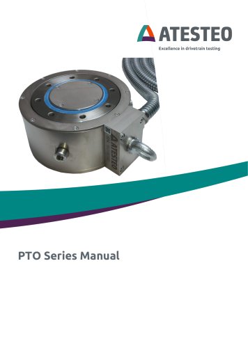
Manual PTO series
This manual provides assembly instructions for the ATESTEO torque meter designed for power take-off (PTO) applications. It includes details for a 75 mm measuring shaft and its customized variants. The instructions should be used alongside the 'VETAS 3' evaluation unit and 'VECTO' configuration software manuals.
Safety Instructions
Before using the torque measurement system, all safety instructions must be read and followed. Only qualified personnel should perform maintenance on electrical components. Key safety measures include wearing protective gear, securing cables, and ensuring the system is operated in a safe environment. The system is not designed for control or safety shutdown purposes.
Measuring Shaft
The system includes a rotor with strain gauges, a toothed ring for speed measurement, and a stator with a flexible shaft sleeve. It uses contactless measurement technology with inductive power supply and signal transmission.
Mechanics
The torque meter is installed between a tractor's drive shaft and a harvesting implement. Proper installation requires specific bolts and tightening torques. The system must accommodate axial movements and ensure water drainage holes are sealed during operation.
Electrical
The VETAS3 unit is modified for operation with the torque meter. Torque and speed signals can be measured via specific outputs. Proper wiring and pin assignments are crucial for signal transmission and power supply.
Maintenance and Care
Maintenance involves disconnecting the VETAS unit, removing water drain screws, and flushing the sensor with clean water. Regular calibration every two years is recommended.
Drawings
Includes technical drawings for the PTO torque meter model MP01-40 90 02 01.
For further information, contact ATESTEO via phone or email.
Catalog excerpts

Excellence in drivetrain testing
Open the catalog to page 1
Operating instructions torque meter for power take off (PTO) Version 1.0 ATESTEO GmbH & Co. KG Konrad-Zuse-Str. 3 52477 Alsdorf Germany Email [email protected] Operating instructions torque meter for power take off (PTO)-Version
Open the catalog to page 2
Operating instructions torque meter for power take off (PTO)-Version 1.0
Open the catalog to page 3
These assembly instructions are intended for the following products: - 75 mm long measuring shaft for fitting to a PTO shaft (drawing numbers MP01-40 90 02 01, MP01-40 90 02 02 or MS093-40 30 02 99) - Customised variants of the above-mentioned measuring intermediate shaft These instructions must be used in conjunction with the manual for the ‘VETAS 3’ evaluation unit and the ‘VECTO’ configuration software. Operating instructions torque meter for power take off (PTO)-Version
Open the catalog to page 4
2 Safety instructions The operating instructions must be read carefully before commissioning, maintenance or any other work on the torque measurement system. Compliance with all safety instructions and safety regulations for the attached equipment is a prerequisite for the safe and proper handling of the device. Only qualified personnel may carry out maintenance work on electrical components. These safety instructions must be included when the torque measurement flange is sold. • Wear safety footwear and gloves during assembly, transport and maintenance. • Tighten the rotor screws to the specified...
Open the catalog to page 5
• Store in a dry, dust-free place • Do not expose to corrosive substances • Protect from direct sunlight • Avoid mechanical shocks • Storage temperature as per the data sheet If the system breaks, there is a risk of fatal injury from flying parts. • Limit torque (exceeding this will cause deformation of the system and consequently lead to permanent measurement errors), • breakage torque (exceeding this leads to dangerous failure of the system), • limit values for rotational speeds, • limits on electrical load capacity. These limits are specified in the product data sheets. Operating instructions...
Open the catalog to page 6
- A rotor fitted with strain gauges for measuring torque. - A toothed ring on the rotor with X pulses per revolution for measuring the rotational speed. The number of pulses depends on the system and can be found in the data sheet and the test report. - Stator with bearing, permanently mounted to the rotor. - A flexible shaft sleeve extending from the stator to protect the signal cables and the power supply cable. - For contactless measurement technology in the rotor, the following is provided between the rotor and the stator: o a wireless power supply (inductive) and o a wireless signal transmission...
Open the catalog to page 7
The torque meter is fitted between the tractor’s drive shaft (tractor side) and the harvesting implement to be connected (tool side / implement side). The bolts and tightening torque specified below (see 3.1.2) must be used for installation. The flange housing acts as the stator. The receiving electronics are installed there. The housing must be secured against rotational movement as far as possible, as this affects the speed signal. The eye bolt (eye bolt for stator mounting) can be used for fixing. Axial movements, for example when the vehicle’s axles compress, must be taken into account. The...
Open the catalog to page 8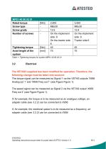
Table 1: Tightening torques for system MP01-40 90 02 01 The torque signal can be measured as Signal 1 via the VETAS outputs ‘X956 Analog out 1’ and ‘X958 Freq out 1’ (see Figure Figure 1). The speed signal can be measured as Signal 2 via the VETAS output ‘X959 Freq out 2’ (see Figure Figure 1). If, for example, the torque is to be measured as an analogue voltage, an adapter cable (see 3.2.2) can be connected to X956. If, for example, the rotational speed is to be measured as a frequency, an adapter cable (see 3.2.2) can be connected to X959. Operating instructions torque meter for power take...
Open the catalog to page 9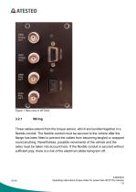
Figure 1 Rear view of VETAS3 Three cables extend from the torque sensor, which are bundled together in a flexible conduit. The flexible conduit must be secured to the vehicle after the flange has been fitted to prevent the cables from becoming tangled or wrapped round anything. Nevertheless, possible movements of the vehicle and the axles must be taken into account here. If the flexible conduit is secured without sufficient play, there is a risk of the electrical cables being torn off. ATESTEO Operating instructions torque meter for power take off (PTO)–Version 1.0
Open the catalog to page 10
The three cables are plugged into the VETAS 3 at their far end. This connects the evaluation unit to the measuring system. Signal transmission and power supply are established. Please refer to the VETAS 3 manual for details of the VETAS 3 power supply. 3.2.2 Pin assignment (data cable) If a data cable (Article code 10004468) has been ordered, this connects a BNC output on the VETAS 3 to the customer’s measurement equipment. The customer has fitted the Phoenix Contact connector 1693416. It has the following pin configuration: Table 2: Pin assignment for adapter cable Operating instructions torque...
Open the catalog to page 11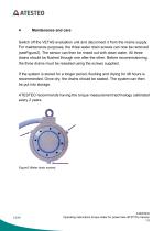
Switch off the VETAS evaluation unit and disconnect it from the mains supply. For maintenance purposes, the three water drain screws can now be removed (seeFigure2). The sensor can then be rinsed out with clean water. All three drains should be flushed through one after the other. Before recommissioning, the three drains must be resealed using the screws supplied. If the system is stored for a longer period, flushing and drying for 48 hours is recommended. Once dry, the drains should be sealed. The system can then be put into storage. ATESTEO recommends having the torque measurement technology...
Open the catalog to page 12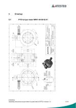
Operating instructions torque meter for power take off (PTO)-Version 1.0 13/14
Open the catalog to page 13
Excellence in drivetrain testing Would you like to find out more about our products, solutions and services in the fields of measurement systems, vehicle equipment and actuators? Then simply give us a call on +49 2404 9870-570 or email us at [email protected]. Your personal ATESTEO contact will be happy to assist you. ATESTEO GmbH & Co. KG Konrad-Zuse-Str. 3 52477 Alsdorf Email [email protected] www.atesteo.com
Open the catalog to page 14All ATESTEO GmbH & Co. KG catalogs and technical brochures
 Data sheet PTO series
14 Pages
 Flyer DF-family
4 Pages
 Data sheet F4 RTS
7 Pages
 Data sheet DF4 ibex
21 Pages
 Data sheet DF5 ibex
21 Pages
 Data sheet F4xS
21 Pages
 Data sheet DF5 dual
23 Pages
 Data sheet DF4 dual
23 Pages
 Data sheet DF3 dual
23 Pages
 Data sheet DF2 dual
23 Pages
 Data sheet DF1 dual
23 Pages
 Manual CapSync HVT
68 Pages
 Data sheet CapSync HVT
7 Pages
 Manual IRTS series
116 Pages
 Data sheet IRTS-P
11 Pages
 Manual VETAS 3
30 Pages
 Manual VECTO
26 Pages
 Manual steering wheel
17 Pages
 Data sheet steering wheel
9 Pages
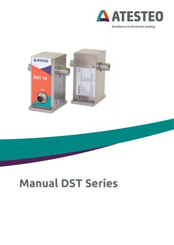 Manual DST series
69 Pages
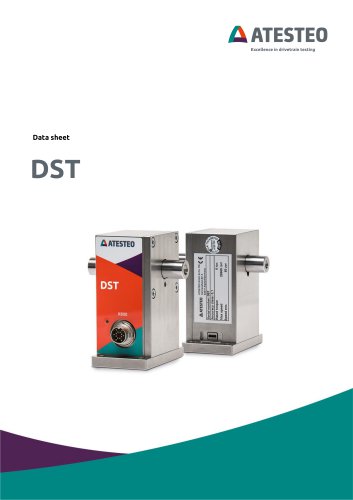 Data sheet DST series
13 Pages
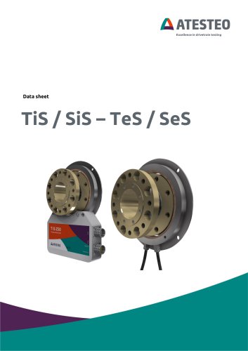 Data sheet TiS Z50
20 Pages
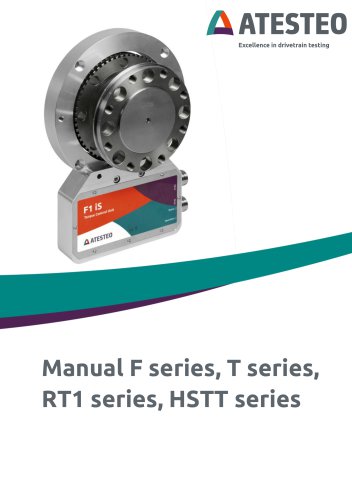 Manual T series
124 Pages
 Data sheet TeS Z50
21 Pages
 Manual RT11 series
124 Pages
 Data sheet RT11eS-B
20 Pages
 Data sheet RT11eS
17 Pages
 Manual HSTTeS series
124 Pages
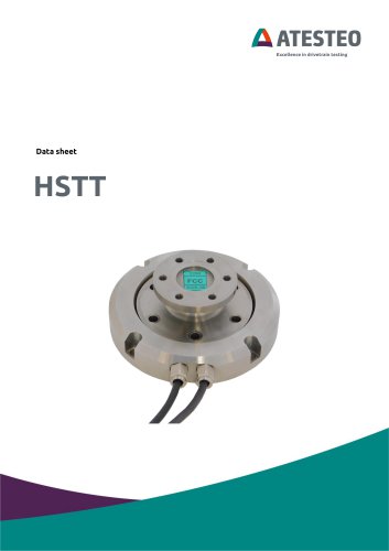 Data sheet HSTTeS series
20 Pages
 Data sheet F23 RTS
7 Pages
 Data sheet F3 RTS
7 Pages
 Data sheet F5xS
18 Pages
 Data sheet F34xS
21 Pages
 Data sheet F3xS
27 Pages
 Data sheet F23xS
21 Pages
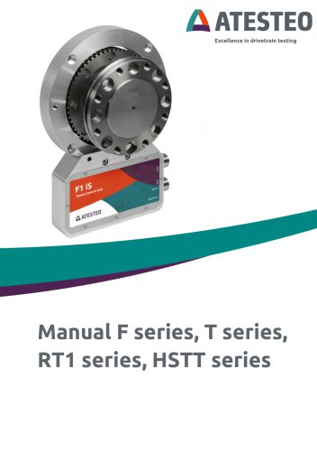
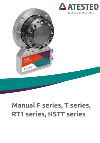 Manual Fx series
124 Pages
 Data sheet F2xS
35 Pages
 Data sheet F1xS
27 Pages
 Data sheet F0xS
51 Pages
 Data sheet F0xS-SV
27 Pages
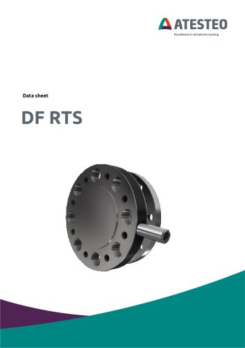 Data sheet DF RTS
11 Pages
 Data sheet DF plus HS
20 Pages
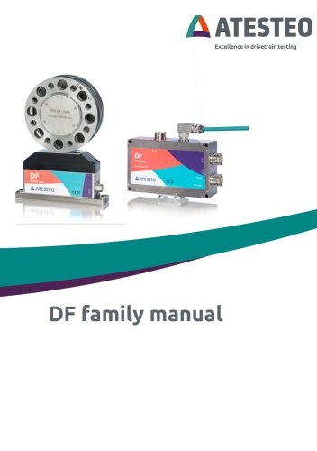 Manual DF plus series
132 Pages
 Data sheet DF plus series
41 Pages
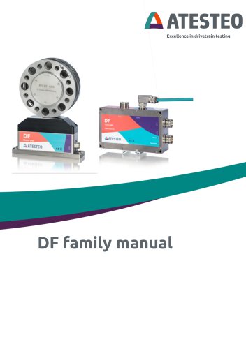 Manual DF dual series
132 Pages
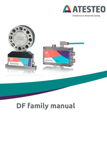 Manual DF ibex series
132 Pages
 Data sheet DF3 ibex
21 Pages
 Data sheet DF2 ibex
21 Pages
 Data Sheet DF1 ibex
21 Pages

- ATESTEO dynamic torque sensor
- ATESTEO rotary torque sensor
- ATESTEO analog torque sensor
- ATESTEO strain gauge torque sensor
- ATESTEO non-contact torque sensor
- ATESTEO digital torque sensor
- ATESTEO high-accuracy torque sensor
- ATESTEO DC torque sensor
- ATESTEO torque sensor with flange connection
- Compact torque sensor
- Modular temperature control
- ATESTEO voltage output torque sensor
- USB torque sensor
- 12VDC torque sensor
- Flange-mounted torque sensor
- ATESTEO test bench torque sensor
- ATESTEO torque sensor with integrated electronics
- Custom torque sensor
- Torque sensor with rotary encoder