- Catalogs
- ATESTEO GmbH & Co. KG
- Manual IRTS series
Manual IRTS series
1 /116Pages
Manual IRTS series
1 /116Pages
Catalog excerpts

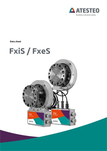
IRTS-P Manual Temperature telemetry system
Open the catalog to page 1
IRTS-P Manual Version 1.1 06.2025 Your contact for service requests ATESTEO GmbH & Co. KG Konrad-Zuse-Str. 3 52477 Alsdorf Germany T +49 (0) 2404 9870-580 [email protected] www.atesteo.com ATESTEO IRTS-P Manual – Version 1.1
Open the catalog to page 2
A ATESTEO Excellence in drivetrain testing 1.7.2 IRTS-P Half Shells 18 2.1 General safety instructions 19 2.2 Explanation of symbols and notice 20 2.7 Safety notes for assembly 26 2.8 Safety notes for operation 27
Open the catalog to page 3
AATESTEO Excellence in drivetrain testing 3.2.1 System overview (electrical) 31 3.2.2 System overview (functional areas) 32 3.2.3 System overview (mechanical) 33 3.3 IRTS-P Half shells 34 3.3.1 System overview (electrical) 34 3.3.2 System overview (Functional areas) 35 3.3.3 System overview (mechanical) 36 3.5.1 Controller test signal 39 4 Mechanical & electrical installation 44
Open the catalog to page 4
A ATESTEO Excellence in drivetrain testing 4.3.1 Mechanical installation IRTS-P Tempdisc 46 4.3.2 Mechanical installation IRTS-P Half shells 55 4.4 Assembly evaluation unit (TCU5) 58 4.5 Grounding at the test bench 61 4.5.1 Stator ground screw 63 4.6 The wiring of the evaluation unit 64 4.7 Power and data cable 66 6.1.1 Temperature channel overview 74
Open the catalog to page 5
AATESTEO Excellence in drivetrain testing 7.2 X771 Analog / CAN / Alarm / Eingang
Open the catalog to page 6
Introduction Thank you for choosing an ATESTEO quality product. Please read the system description carefully so you make the most of the versatile features of your product. This operating manual is a component of the IRTS-P system and should always be carefully kept with the IRTS-P system until it is disposed of. It is impossible to eliminate every danger to persons or material that the IRTS-P system might present. For this reason, every person working at the IRTS-P system or is involved in its transport, setting up, control, maintenance or repair must be properly instructed and be informed of...
Open the catalog to page 7
AATESTEO Excellence in drivetrain testing The brands mentioned in this operator's manual and product names are trademarks or registered trademarks of the respective titleholders. Please do not miss to contact us if there is anything in the operating instructions that you cannot clearly understand. We are grateful for any kind of suggestion or criticism that you may wish to make. Please let us know or write to us. This will help us to make the operating instruction still more user-friendly in taking account of your wishes and requirements. • Safety notes for high voltage from third party components...
Open the catalog to page 8
side-by-side attached to a torquemeter. Temperature sensors are usually supplied by the customer and are not part of the IRTS-P system since they are often pre-installed in specimen or devices. 1.2.1 The temperatures at the measuring points are measured with simple type K sensors. Electronics on the rotating side (sender) is connected to the sensors and is responsible for processing the measurement signals. The sender transmits the measured temperatures digitally via an optical transmission system to the IRTS stator. This supplies the sender at the same time inductively with voltage. The transferred...
Open the catalog to page 9
to which each a temperature measuring channel with an individual temperature range can be assigned. One measuring channel can also be selected for several analogue outputs and be configured with different filters. This enables an optimal design of the system to the respective customer needs. Note Please note that the IRTS-P system is a high-precision measuring instrument. Mechanical effects e.g. hammer impacts lead to deformation of the measuring body, which changes its torsional behavior and thus worsens the balancing! Before mounting, make sure that the fits of your adapters comply with the...
Open the catalog to page 10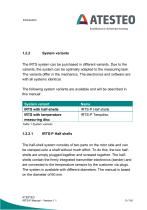
A ATESTEO Excellence in drivetrain testing The IRTS system can be purchased in different variants. Due to the variants, the system can be optimally adapted to the measuring task. The variants differ in the mechanics. The electronics and software are with all systems identical. The following system variants are available and will be described in this manual: Table 1 System variants The half-shell system consists of two parts on the rotor side and can be clamped onto a shaft without much effort. To do this, the two halfshells are simply plugged together and screwed together. The halfshells contain...
Open the catalog to page 11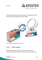
The stator consists of an electronics housing, a "gooseneck" for data transmission and a copper ring for power supply. Figure 1 System variant IRTS-P with half-shells IRTS-P Tempdisc The IRTS tempdisc has a disc on the rotor side on which the electronics (sender) are installed. The disc is fixed to a machine and ATESTEO IRTS-P Manual – Version 1.1
Open the catalog to page 12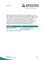
A ATESTEO Excellence in drivetrain testing optionally screwed to a suitable torque measuring flange (e. g. TeS Z50 or SeS Z50). The temperature disc is supplied with voltage via the "eS" ring stator. The received data are sent from the ring stator to the IRTS stator. The temperature disc variant comes in different constructions (designs). Electronic installation and functionality are mostly identical. Mechanical installation may differ between the siblings. This manual focusses on the following design type: Table 2 Design type of IRTS-P Tempdisc
Open the catalog to page 13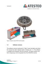
Figure 2 System variant IRTS-P with tempdisc Software versions The software versions mentioned in Table 3 were the latest ones when this manual has been released (date of release see 1.1). The software is updated more frequently than the manuals. The latest versions incl. their change logs can be requested from the ATESTEO service. ATESTEO IRTS-P Manual – Version 1.1
Open the catalog to page 14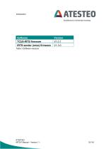
A ATESTEO Excellence in drivetrain testing Table 3 Software versions
Open the catalog to page 15
A ATESTEO Excellence in drivetrain testing ATESTEO GmbH & Co.KG (Hereinafter referred to as manufacturer) Konrad-Zuse-Str. 3 52477 Alsdorf Germany The manufacturer declaration can be requested at ATESTEO.
Open the catalog to page 16
Electrical and electronic products are subject to special conditions for disposal. Proper disposal of old equipment prevents health hazards and environmental damage. Packaging The original packaging of ATESTEO equipment can be recycled, as it is made of recyclable material. However, you should keep the packaging for at least the warranty period. In the event of a complaint, the torque flange, as well as the accessories, must be returned in the original packaging. Legally prescribed labelling for disposal Electrical and electronic devices bearing the symbol are subject to European Directive 2002/96...
Open the catalog to page 17All ATESTEO GmbH & Co. KG catalogs and technical brochures
 Data sheet DF4 ibex
21 Pages
 Data sheet DF5 ibex
21 Pages
 Data sheet F4xS
21 Pages
 Data sheet DF5 dual
23 Pages
 Data sheet DF4 dual
23 Pages
 Data sheet DF3 dual
23 Pages
 Data sheet DF2 dual
23 Pages
 Data sheet DF1 dual
23 Pages
 Manual CapSync HVT
68 Pages
 Data sheet CapSync HVT
7 Pages
 Data sheet IRTS-P
11 Pages
 Manual VETAS 3
30 Pages
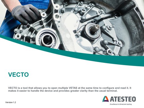 Manual VECTO
26 Pages
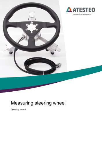 Manual steering wheel
17 Pages
 Data sheet steering wheel
9 Pages
 Manual DST series
69 Pages
 Data sheet DST series
13 Pages
 Data sheet TiS Z50
20 Pages
 Manual T series
124 Pages
 Data sheet TeS Z50
21 Pages
 Manual RT11 series
124 Pages
 Data sheet RT11eS-B
20 Pages
 Data sheet RT11eS
17 Pages
 Manual HSTTeS series
124 Pages
 Data sheet HSTTeS series
20 Pages
 Data sheet F23 RTS
7 Pages
 Data sheet F3 RTS
7 Pages
 Data sheet F5xS
18 Pages
 Data sheet F34xS
21 Pages
 Data sheet F3xS
27 Pages
 Data sheet F23xS
21 Pages
 Manual Fx series
124 Pages
 Data sheet F2xS
35 Pages
 Data sheet F1xS
27 Pages
 Data sheet F0xS
51 Pages
 Data sheet F0xS-SV
27 Pages
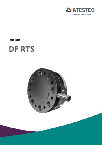 Data sheet DF RTS
11 Pages
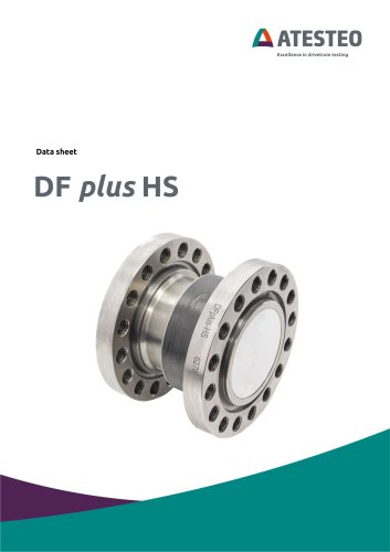 Data sheet DF plus HS
20 Pages
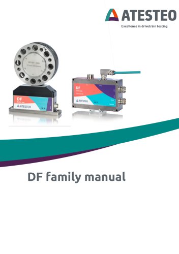
 Manual DF plus series
132 Pages
 Data sheet DF plus series
41 Pages
 Manual DF dual series
132 Pages
 Manual DF ibex series
132 Pages
 Data sheet DF3 ibex
21 Pages
 Data sheet DF2 ibex
21 Pages
 Data Sheet DF1 ibex
21 Pages
- Torque transducer
- Dynamic torque sensor
- Rotary torque sensor
- Analog torque sensor
- Strain gauge torque sensor
- DC torque sensor
- Non-contact torque sensor
- Digital torque sensor
- High-accuracy torque sensor
- Torque sensor with flange connection
- Modular temperature control
- Voltage output torque sensor
- Compact torque sensor
- 12VDC torque sensor
- USB torque sensor
- Flange-mounted torque sensor
- Custom torque sensor
- Test bench torque sensor
- Torque sensor for the automobile industry
- 24VDC torque sensor