
- Catalogs
- ATESTEO GmbH & Co. KG
- Manual Fx series

- Company
- Products
- Catalogs
- News & Trends
- Exhibitions
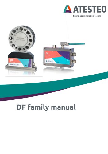
Manual Fx series
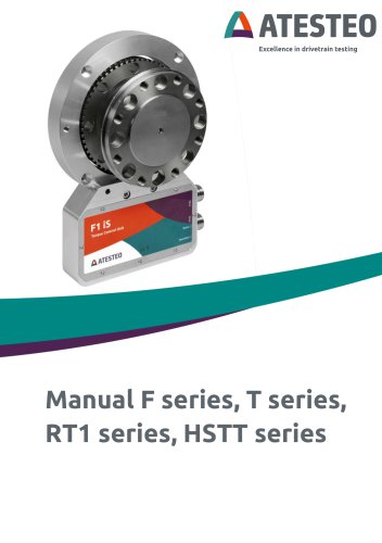
Manual Fx series
ATESTEO GmbH & Co. KG, based in Alsdorf, Germany, manufactures the torque and speed measurement systems detailed in this manual. Contact can be made via phone or email for assistance.
The manual's latest version is V1.3, dated 04.09.2025, featuring updates like visual optimization of the grounding scheme, alignment of technical data with data sheets, and the addition of product F34xS.
This manual provides startup instructions for ATESTEO torque meters, including F, T, RT1, and HSTT series. These systems are contactless, maintenance-free, and use frequency modulated infrared transmitters for data transmission.
Electrical and electronic products must be disposed of according to regulations to prevent environmental damage. The original packaging is recyclable and should be retained during the warranty period.
Detailed parts lists for different torque meter models are included, specifying components like the torque meter rotor, stator, connectors, and optional calibration certificates.
Users must read the manual thoroughly before operating the system. Safety instructions emphasize proper installation, maintenance by qualified personnel, and adherence to relevant standards and directives.
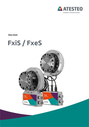
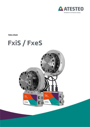
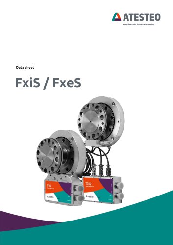
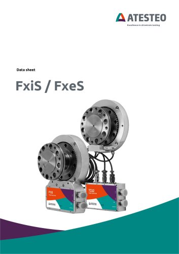
The F series torque measurement systems are designed for high accuracy and stability, with some models featuring inductive speed measurement systems. Different stator types (iS and eS) and their configurations are described.
Key parameters include a 24V DC power supply, dynamic frequency and voltage outputs, and various output signal options. Telemetry systems and measurement ranges for the torque meters are detailed.
Recommendations include wearing safety shoes and gloves when handling corrosive materials and ensuring proper storage conditions to maintain equipment integrity.
System parameters accessible via RS232 and CAN 2B interface are outlined, highlighting dual-channel capabilities, specifically the second channel (DT2) for precise measurement of small torques.
The dual telemetry system includes a second amplifier and infrared transmission, enabling accurate measurement of both high and low torques, supporting parallel use of two measuring ranges.
Advice is given on using the second measuring range for tasks where sensor replacement is not feasible, warning of potential measurement errors due to parasitic influences.
A table lists compatibility of various measuring systems with single-channel telemetry, second measuring range (DT2), and double telemetry (DT).
The system includes functions like self-test, zero adjustment, test signal generation, supply search process, and alerts for maximum safe operating conditions.
Three types of speed detection systems are described: inductive, magnetic, and optical, each providing RS422 signals and processed values for analogue outputs and CAN messages.
A test report accompanies each torque meter, detailing operational parameters, sensitivities, and test signals. Factory and DAkkS calibration sheets provide sensitivity data.
LED indicators provide status information: a green LED indicates normal operation, while a red LED signals errors or ongoing processes.
Guidelines for mechanical installation of components are provided, emphasizing handling and alignment, with instructions for transporting, lifting, and installing rotors and stators.
Specifications for various series of torque measurement systems are provided, including nominal torque values, screw types, screw quality, and corresponding tightening torques.
Installation procedures for speed detection systems are outlined, with specific instructions for setting distances and mounting components.
Recommendations for electrical installation include using specific cable types and ensuring proper grounding.
Tables provide key data, such as tightening torques for screws across different series and thread sizes with screw-in depths.
Important parameters include nominal torque values, screw quality, and tightening torques, crucial for proper installation and operation.
Detailed specifications for cable connections, including RS232, RS422, and CAN interfaces, are provided.
Various electrical circuits are outlined, emphasizing the importance of disconnecting the RS232 connection during operation, except for configuration purposes.
Guidance for initial installation of torque measurement systems is provided, highlighting the necessity of entering operating parameters from the test report using TCU-Config software.
Details on using TCUConfig software for configuring torque meters are included, with steps for setting up inductive power supply, torque zero adjustment, test signals, calibration parameters, and analogue outputs.
Instructions for setting up the CAN interface, including selecting signals, data rates, and identifiers, are provided.
If TCUConfig is unavailable, settings can be adjusted using a terminal program, with key descriptions for zero calibration, test signal activation, filter settings, alarm thresholds, and output configurations.
Details on digital filter settings for torque and speed channels are provided, including cut-off frequencies and moving average filter depths.
Configuration of analogue and CAN outputs is explained, including setting identifiers and sampling rates.
Instructions for setting calibration parameters and performing zero adjustments are included, emphasizing the importance of adjusting the inductive power supply for new installations.
Procedures for reading and setting calibration parameters for torque meters are outlined, with a self-test procedure described.
The analogue setup allows for adjustment of offset voltage and output voltage range, with CAN setup detailing customization of the CAN interface.
Overvoltage protection mechanisms are in place, and regular calibration of torque meters is recommended.
Details on special DT2 functions, such as channel selection using external signals or a terminal program, are included.
The process for selecting and configuring channels in the ATESTEO measurement systems is outlined, focusing on the DT2 channel.
Switching between channels can be done via terminal or CAN interface, with examples of CAN messages for channel selection provided.
Examples of CAN setup and output settings are included, illustrating how to send and receive messages to select channels.
Numerous figures and tables provide visual guidance and technical data.
The manufacturer's declaration can be requested from ATESTEO service.
Contact details for ATESTEO GmbH & Co. KG are provided for further inquiries or service requests.
Catalog excerpts

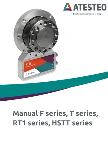
Manual F series, T series, RT1 series, HSTT series
Open the catalog to page 1
Manual F series, T series, RT1 series, HSTT series Version V1.3 Your contact for service requests ATESTEO GmbH & Co. KG Konrad-Zuse-Straße 3 52477 Alsdorf Germany Phone +49 (0) 2404 9870-580 E-Mail [email protected] www.atesteo.com ATESTEO Manual F series, T series, RT1 series, HSTT series – Version V1.3
Open the catalog to page 2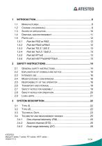
Manual F series, T series, RT1 series, HSTT series -Version V1.3
Open the catalog to page 3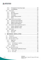
Manual F series, T series, RT1 series, HSTT series -Version V1.3
Open the catalog to page 4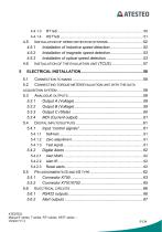
5.2 Connecting torque meter/evaluation unit with the data Manual F series, T series, RT1 series, HSTT series -Version V1.3
Open the catalog to page 5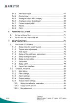
Manual F series, T series, RT1 series, HSTT series -Version V1.3
Open the catalog to page 6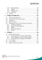
Manual F series, T series, RT1 series, HSTT series -Version V1.3
Open the catalog to page 7
Thank you for choosing an ATESTEO GmbH & Co. KG quality product. Please read the system description carefully so you make the most of the versatile features of your product. These operating instructions are an integral part of the F series and all derivatives of the F series (see 1.3) and should always be carefully kept with the F series until it is disposed of. It is impossible to eliminate every danger to people and/or material that the F series might present. For this reason, every person working at the F series or is involved in its transport, setting up, control, maintenance or repair must...
Open the catalog to page 8
The brands mentioned in this operator's manual and product names are trademarks or registered trademarks of the respective title holders. Please do not miss contacting us if there is anything in the operating instructions that you cannot clearly understand. We are grateful for any kind of suggestion or criticism that you may wish to make; please let us know or write to us. This will help us to make the operating instruction still more user-friendly in taking account of your wishes and requirements. ATESTEO GmbH & Co. KG Konrad-Zuse-StraGe 3 52477 Alsdorf Germany • “Grounding scheme” visually...
Open the catalog to page 9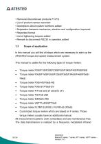
• Removed discontinued products F1i/F2i • List of product names reworked • Description about system functions added • Separation between mechanics, electrics and configuration improved • Reworked format • List of tightening torques added • Remark to disconnect RS232 in operation added In this manual you will find all steps which are necessary to start-up the ATESTEO torque and speed measurement system. This manual is usable for the following types of torque meters: • Torque meter RT 1eS and all variants of it • Torque meter TiS/TeS Z50 • Torque meter SiS/SeS Z50 • Customized torque meters which...
Open the catalog to page 10
transmitter. The power of the rotating electronic module works inductive. The system FLFM1iS is only named F0iS in this document since they are technical the same. The system FLFM1eS is only named F0eS in this document since they are technical the same. Information With this product, you received an information sheet with the default settings. 1.4 Electrical and electronic products are subject to special conditions for disposal. Proper disposal of old equipment prevents health hazards and environmental damage. Packaging The original packaging of ATESTEO equipment can be recycled, as it is made...
Open the catalog to page 11
Electrical and electronic devices bearing the symbol / are subject to the European Directive 2002/96 / EC on waste electrical and electronic equipment. The symbol indicates that waste equipment that is no longer usable must be disposed of separately from regular household waste in accordance with European environmental protection and recycling regulations. However, the disposal regulations vary from country to country, which is why we ask you, if necessary, your supplier how to dispose of your waste. The complete system comes with: • Torque meter (rotor) • Stator All-in-one (integrated evaluation...
Open the catalog to page 12
• TCU2 (Torque Control Unit, external evaluation unit) • Male connector with 16 pins (data cable optional) • Female connector with 12 pins (central cable optional) • Test report (with sensitivity and test signal values) • Optional: Calibration certificate (DAkkS or factory standard) Manual F series, T series, RT1 series, HSTT series -Version V1.3
Open the catalog to page 13
Safety Instructions General safety instructions The manual must be read carefully before starting up, maintenance work or any other work on the torque measuring system. The prerequisite for the safe and proper handling of the equipment knows all safety instructions and safety regulations of the attachment. Every safeguard needs to be correctly mounted and fully functional before any start-up. Shafts or adapters mounted to the torque meter must be properly designed, so that critical bending moment is avoided. Exclusively qualified laborers are allowed to do maintenance work on any electrical components...
Open the catalog to page 14
Explanation of symbols and notice Warnings Warnings are indicated by symbols in these safety instructions. Signal words are introduced, which express the extent of the hazard. It is imperative that you follow the instructions and act with care to avoid accidents, personal injury and material damage. Information Draws attention to important information about correct handling. Caution Warns of a potentially dangerous situation in which failure to comply with safety requirements can result in slight or moderate physical injury. ATESTEO Manual F series, T series, RT1 series, HSTT series – Version...
Open the catalog to page 15
The torque meter is highly accurate and resistant to rotational speed. The signals from the flange serve to control the test bench and to analyze the components. The torque flange is used just for torque measurement tasks within the load limits in the specification (see separate data sheet and 3.3). Any other use is not permitted. The torque meter is not allowed for use as a safety component. Note Stator operation is only permitted if the rotor is installed as described in the mounting instruction. Modifications / conversions Any modifications / conversions of the design or safety engineering...
Open the catalog to page 16All ATESTEO GmbH & Co. KG catalogs and technical brochures
 Flyer DF-family
4 Pages
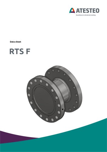 Data sheet F4 RTS
7 Pages
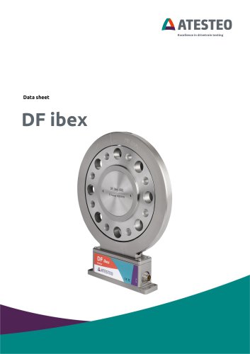 Data sheet DF4 ibex
21 Pages
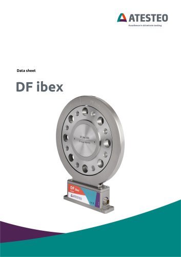 Data sheet DF5 ibex
21 Pages
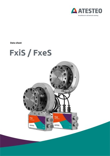 Data sheet F4xS
21 Pages
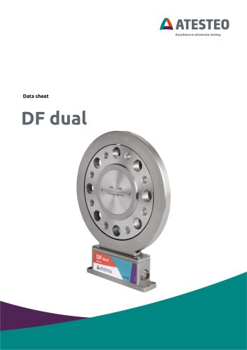 Data sheet DF5 dual
23 Pages
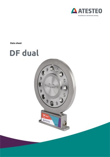 Data sheet DF4 dual
23 Pages
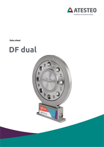 Data sheet DF3 dual
23 Pages
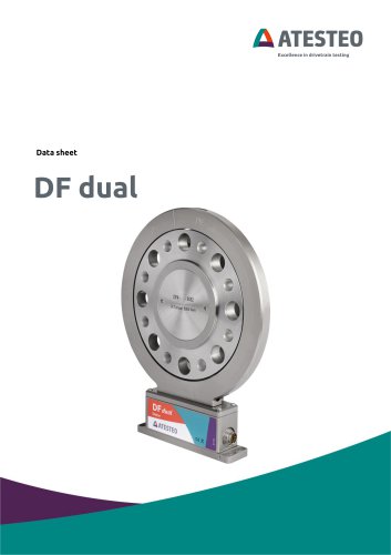 Data sheet DF2 dual
23 Pages
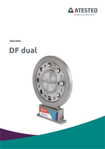 Data sheet DF1 dual
23 Pages
 Manual CapSync HVT
68 Pages
 Data sheet CapSync HVT
7 Pages
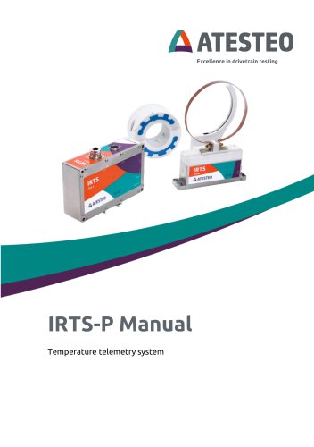 Manual IRTS series
116 Pages
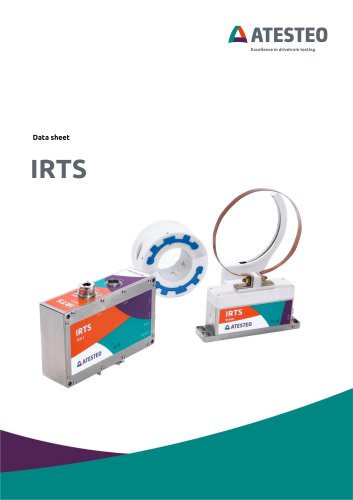 Data sheet IRTS-P
11 Pages
 Manual VETAS 3
30 Pages
 Manual VECTO
26 Pages
 Manual steering wheel
17 Pages
 Data sheet steering wheel
9 Pages
 Manual DST series
69 Pages
 Data sheet DST series
13 Pages
 Data sheet TiS Z50
20 Pages
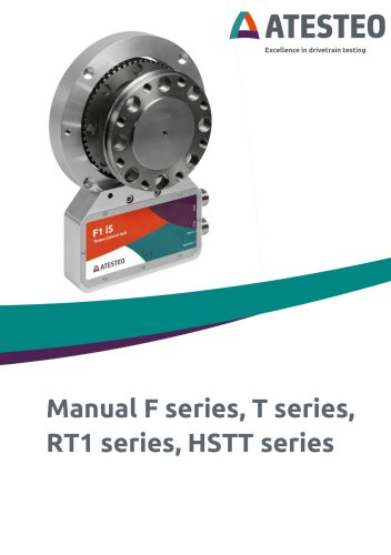 Manual T series
124 Pages
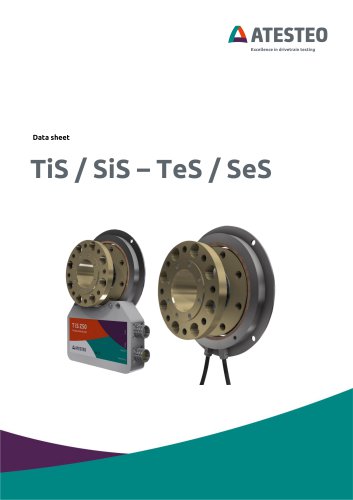 Data sheet TeS Z50
21 Pages
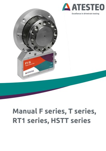 Manual RT11 series
124 Pages
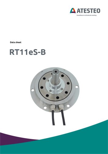 Data sheet RT11eS-B
20 Pages
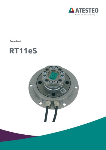 Data sheet RT11eS
17 Pages
 Manual HSTTeS series
124 Pages
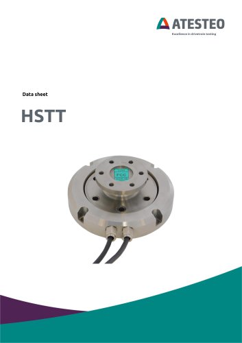 Data sheet HSTTeS series
20 Pages
 Data sheet F23 RTS
7 Pages
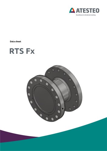 Data sheet F3 RTS
7 Pages
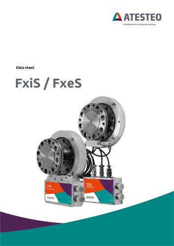 Data sheet F5xS
18 Pages
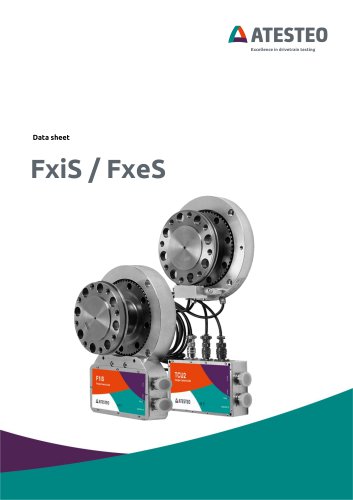 Data sheet F34xS
21 Pages
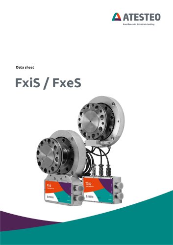 Data sheet F3xS
27 Pages
 Data sheet F23xS
21 Pages
 Data sheet F2xS
35 Pages
 Data sheet F1xS
27 Pages
 Data sheet F0xS
51 Pages
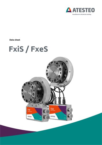 Data sheet F0xS-SV
27 Pages
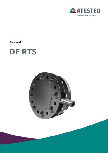 Data sheet DF RTS
11 Pages
 Data sheet DF plus HS
20 Pages
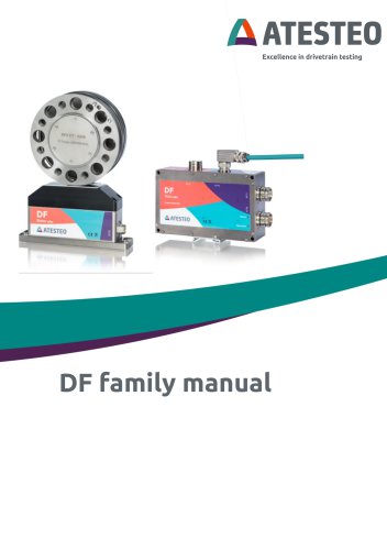 Manual DF plus series
132 Pages
 Data sheet DF plus series
41 Pages
 Manual DF dual series
132 Pages
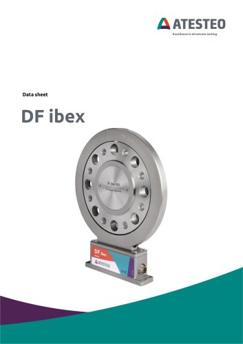
 Manual DF ibex series
132 Pages
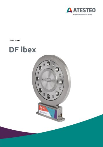
 Data sheet DF3 ibex
21 Pages
 Data sheet DF2 ibex
21 Pages
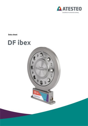 Data Sheet DF1 ibex
21 Pages

- ATESTEO torque sensor
- ATESTEO dynamic torque sensor
- ATESTEO rotary torque sensor
- ATESTEO analog torque sensor
- ATESTEO strain gauge torque sensor
- ATESTEO non-contact torque sensor
- ATESTEO digital torque sensor
- ATESTEO high-accuracy torque sensor
- ATESTEO DC torque sensor
- ATESTEO torque sensor with flange connection
- Compact torque sensor
- Modular temperature control
- ATESTEO voltage output torque sensor
- USB torque sensor
- 12VDC torque sensor
- Flange-mounted torque sensor
- ATESTEO test bench torque sensor
- ATESTEO torque sensor with integrated electronics
- Custom torque sensor
- Torque sensor with rotary encoder