
- Catalogs
- ATESTEO GmbH & Co. KG
- Manual DST series

- Company
- Products
- Catalogs
- News & Trends
- Exhibitions
Manual DST series
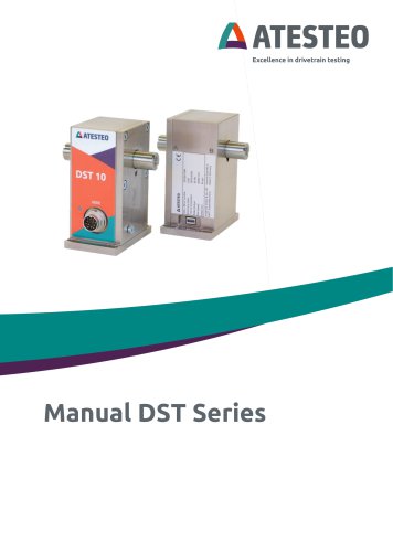
Manual DST series
The manual provides detailed instructions for the ATESTEO DST series torque and speed measurement system, emphasizing safety and proper handling to prevent hazards. ATESTEO reserves the right to make product changes without explicit documentation.
Updates from version 1.0 to 1.5 include added part numbers, corrected information, and updated product pictures.
ATESTEO GmbH & Co. KG, located in Alsdorf, Germany, is the manufacturer. Contact details are provided for assistance.
The manual covers start-up procedures for DST torquemeter models, which are maintenance-free and use contactless data transfer.
Instructions for proper disposal of electronic products comply with European Directive 2002/96/EC.
- General Safety: The manual must be read before operation. Only qualified personnel should perform maintenance.
- Symbols and Notices: Various symbols indicate warnings and important information.
- Appropriate Use: The torquemeter is designed for specific tasks and should not be used as a safety component.
- Modifications: Unauthorized modifications void warranties and liabilities.
- Operator's Responsibility: Operators must ensure safety standards are met and minimize residual risks.
The system integrates torque and speed measurement technologies, allowing data recording via USB or analogue voltage output with high dynamic frequency output for precise measurements.
Operates on a 24V DC power supply with a sample rate for torque signals from 2 to 2,000 samples per second. Measures speeds from 1 rpm to 30,000 rpm, with mechanical limits at 20,000 rpm. Offers selectable analogue output ranges and a 16-bit resolution.
Includes disturbance-insensitive IR transmission, adjustable torque sampling rates, frequency outputs proportional to torque and speed, overvoltage protection, analogue voltage output, zero adjustment, test signal functionality, simulation values, and strain gauge short circuit capabilities.
Mechanical installation requires mounting the DST on a fixed ground using M5 screws. Electrical installation involves connecting to a 24-30V DC power supply and ensuring proper earthing. Connect to a data acquisition system using shielded cables.
Connects to a computer via USB/UART interface with specific port settings. Commands adjust settings like torque sampling rate, DAC range, and activate test signals or simulated values. Supports data transfer and display of datasheets via UART interface.
Describes parameter transmission where frequency output is not fixed. The stator generates a data sheet from rotor and stator parameters, sent via UART interface.
Reserved for calibration, including commands ‘C’, ‘P’, ‘V’, “X”, “Y”.
Data stream is ASCII coded in CSV format, customizable update rate (2 Hz to 2 kHz). Parameters include Watchdog, torque, speed, and system-state.
Increments with each new line, cycling from zero to nine.
Displayed as a relative value in Hz, limited to ±120% of nominal torque.
Given in rpm with one decimal place.
Consists of 14 ASCII characters, each representing a system component's state.
Initiated by the ‘S’ key, transmitted via UART. Contains serial number, firmware versions, rated torque, sensitivity, rotor supply voltage, temperature, and error codes.
Includes zero adjustment, test signal activation, and alarm-out functions.
System status indicated via LED colors and frequencies.
Connects DST with Windows™ PC software for various functions like checking states, showing torque and speed values, changing settings, and acquiring data.
Program settings allow changes to chart scaling, GUI options, trace settings, and sensitivity sources. DST settings include sampling rate and DAC output range.
Divided into areas for connection, status, chart, data, and log messages.
Includes procedures for updating data from the rotor, converting torque signals from Hz to Nm, and the importance of firmware and serial numbers for service inquiries.
Data area shows torque and speed measurements, with states indicated by LED colors.
Records events such as warnings, errors, and user actions.
Details on plug connections at DST, including X800 and USB connectors.
Outlines conditions for zero-resetting, emphasizing it should only be done when torque is zero.
Mentions the CE Manufacturer’s Declaration as a separate document available on request.
Includes tables and figures referenced throughout the manual.
Catalog excerpts
Excellence in drivetrain testing
Open the catalog to page 1
ATESTEO GmbH & Co. KG Konrad-Zuse-Str. 3 52477 Alsdorf Germany Telephone E-Mail [email protected] www.atesteo.com ATESTEO Manual DST – Version V1.5
Open the catalog to page 2
List of content 1 Introduction 6 2.1 General safety instructions 10 2.2 Explanation of symbols and notice 11 2.6 Safety notes for assembly 16 2.7 Safety notes for operation 16 3.2.1 Speed measuring system 21 3.2.3 Analogue voltage output 21 3.2.7 Strain gauge short circuit 23 3.2.8 Nominal value adjustment 23
Open the catalog to page 3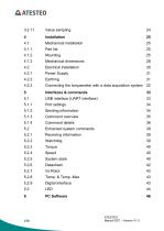
4.2.3 Connecting the torquemeter with a data acquisition system 32 5.1 USB interface (UART interface) 33 5.2 Enhanced system commands 39
Open the catalog to page 4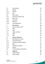
6.3.1 Connect & configure area 53 8.1 Resetting the zero point 61 8.1.4 Lateral force influence 62
Open the catalog to page 5
ATESTEO Manual DST – Version V1.5
Open the catalog to page 6
Thank you for choosing ATESTEO GmbH & Co. KG quality product. Please read the system description carefully so you make the most of the versatile features of your product. This operating manual is a component of the DST series and should always be carefully kept with the DST series until it is disposed of. It is impossible to eliminate every danger to persons or material that the DST series might present. For this reason, every person working at the DST series or is involved in its transport, setting up, control, maintenance or repair must be properly instructed and be informed of the possible...
Open the catalog to page 7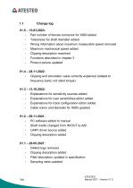
- Part number of female connector for X800 added - Tolerances for shaft diameter added - Wrong information about maximum measurable speed removed - Maximum mechanical speed added - Clipping description reworked - Functions described in chapter 3 - Product picture updated - Clipping and simulation value correctly explained (related to frequency band, not rated torque) - Explanations for sensitivity sources added - Explanations for user sensitivities editor added - Explanations for trace configuration editor added - Cable colors and diameter for X800 updated - PC software added to manual - Shaft...
Open the catalog to page 8
- UART driver installation information added - First version ATESTEO GmbH & Co. KG Konrad-Zuse-StraGe 3 52477 Alsdorf Germany Service: [email protected] In this manual you will find all steps which are necessary to start-up the ATESTEO torque and speed measurement system. This manual is usable for the following types of torquemeter: Torquemeter DST 5 Torquemeter DST 10 Torquemeter DST 20 All measurement systems work contactless and are maintenance-free. The data transfer is realized by a frequency modulated infrared transmitter. The power of the rotating electronic module works inductive....
Open the catalog to page 9
Electrical and electronic products are subject to special conditions for disposal. Proper disposal of old equipment prevents health hazards and environmental damage. Packaging The original packaging of ATESTEO equipment can be recycled, as it is made of recyclable material. However, you should keep the packaging for at least the warranty period. In the event of a complaint, the torque flange, as well as the accessories, must be returned in the original packaging. Due to ecological aspects, the return of the empty packaging should be waived. Legally prescribed labeling for disposal Electrical...
Open the catalog to page 10
Safety Instructions General safety instructions The manual must be read carefully before start-up, maintenance work or any other work on the torque measuring system. Prerequisite for the safe and proper handling of the equipment knows all safety instructions and safety regulations of the attachment. Every DST needs to be correctly mounted and fully functional before any start-up. Shafts or adapters mounted to the torquemeter must be properly designed, so that critical bending moment is avoided. Exclusively qualified laborers are allowed to do maintenance work on any electrical components (see...
Open the catalog to page 11
Explanation of symbols and notice Warnings Warnings are indicated by symbols in these safety instructions. The hints are going through Signal words are introduced, which express the extent of the hazard. It is imperative that you follow the instructions and act with care to avoid accidents, personal injury and material damage. Information Draws attention to important information about correct handling. Caution Warns of a potentially dangerous situation in which failure to comply with safety requirements can result in slight or moderate physical injury. ATESTEO Manual DST – Version V1.5
Open the catalog to page 12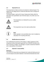
The torquemeter is highly accurate and resistant to rotational speed. The signals from the flange serve to control the test bench and to analyze the components. The torque flange is used just for torque measurement tasks within the load limits in the specification (see Technical specs). Any other use is not permitted. The torquemeter is not allowed for use as a safety component. The torquemeter may not be used as pillow block. Note Stator operation is only permitted when rotor is installed as described in the mounting instruction. Any modifications/conversions of the design or safety engineering...
Open the catalog to page 13
technical specifications with which it complies. It represents the state of the art and guarantees a maximum degree of safety. Qualified personnel Qualified personnel are persons who by reason of their training, experience, instruction and their knowledge of the relevant standards, regulations, accident prevention rules and working conditions have been authorized by the person responsible for the safety of the machine/product to perform the appropriate activities required, and thereby are able to recognize and prevent potentially dangerous situations (For the definition of skilled workers see...
Open the catalog to page 14
Attention should be drawn to residual risks associated with torque measuring technology. In the case of a shaft break, you must ensure that there is no risk of injury. This should be done with a shaft protection cover in a closed test room with corresponding security doors. During operation, no person should stay in the test room. Usage recommendations for personal protective equipment Working in a workshop generally requires the wearing of safety shoes. Use suitable gloves when handling corrosive or irritating solutions and adhesives. ATESTEO Manual DST – Version V1.5
Open the catalog to page 15All ATESTEO GmbH & Co. KG catalogs and technical brochures
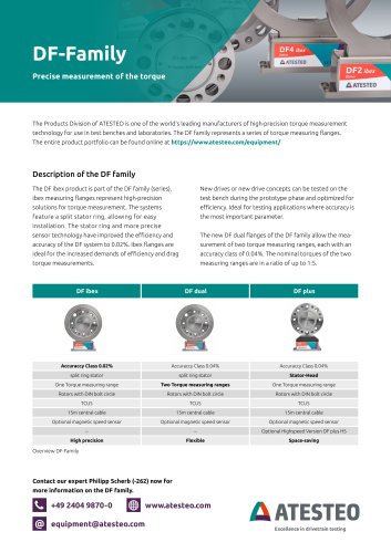 Flyer DF-family
4 Pages
 Data sheet F4 RTS
7 Pages
 Data sheet DF4 ibex
21 Pages
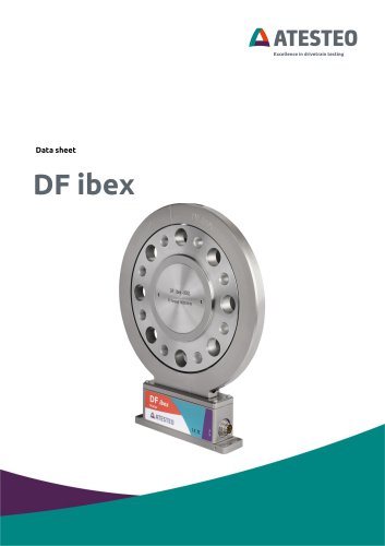 Data sheet DF5 ibex
21 Pages
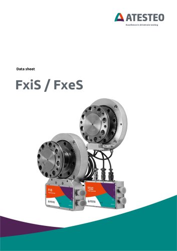 Data sheet F4xS
21 Pages
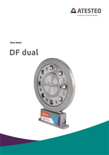 Data sheet DF5 dual
23 Pages
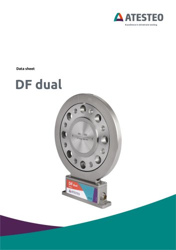 Data sheet DF4 dual
23 Pages
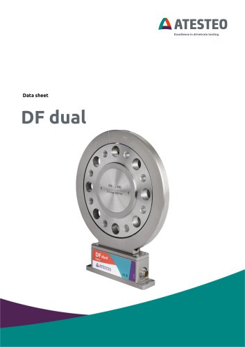 Data sheet DF3 dual
23 Pages
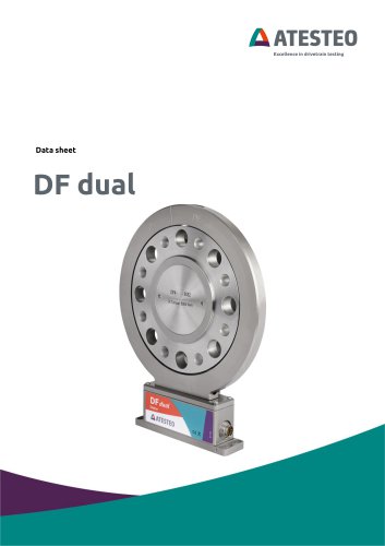 Data sheet DF2 dual
23 Pages
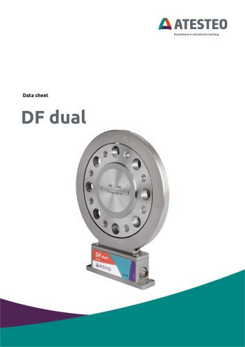 Data sheet DF1 dual
23 Pages
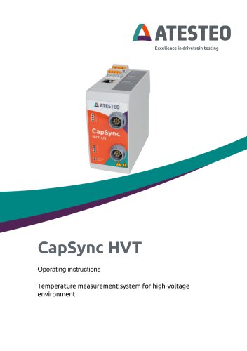 Manual CapSync HVT
68 Pages
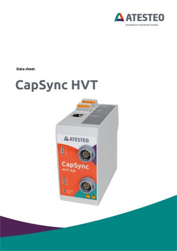 Data sheet CapSync HVT
7 Pages
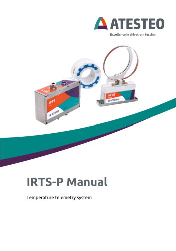 Manual IRTS series
116 Pages
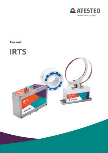 Data sheet IRTS-P
11 Pages
 Manual VETAS 3
30 Pages
 Manual VECTO
26 Pages
 Manual steering wheel
17 Pages
 Data sheet steering wheel
9 Pages
 Data sheet DST series
13 Pages
 Data sheet TiS Z50
20 Pages
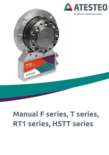 Manual T series
124 Pages
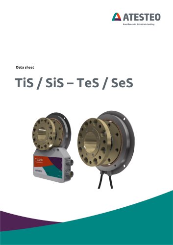 Data sheet TeS Z50
21 Pages
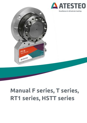 Manual RT11 series
124 Pages
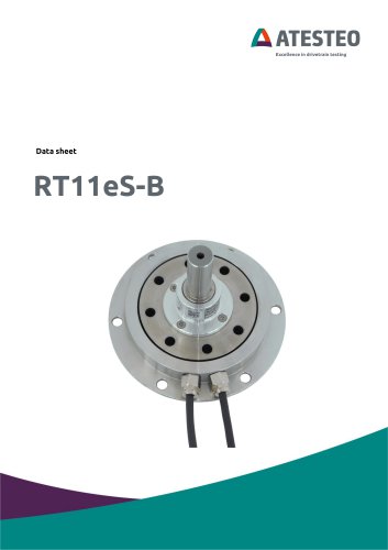 Data sheet RT11eS-B
20 Pages
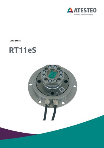 Data sheet RT11eS
17 Pages
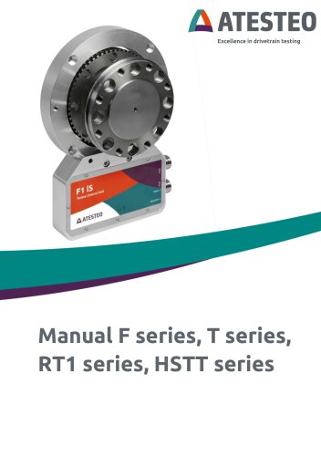 Manual HSTTeS series
124 Pages
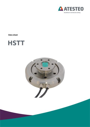 Data sheet HSTTeS series
20 Pages
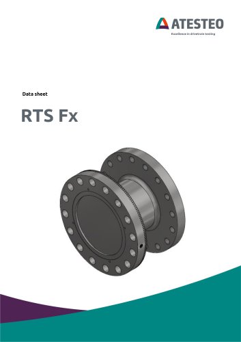 Data sheet F23 RTS
7 Pages
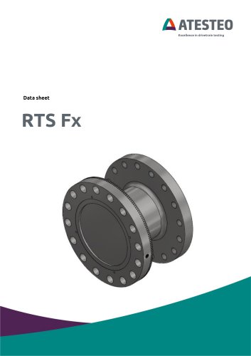 Data sheet F3 RTS
7 Pages
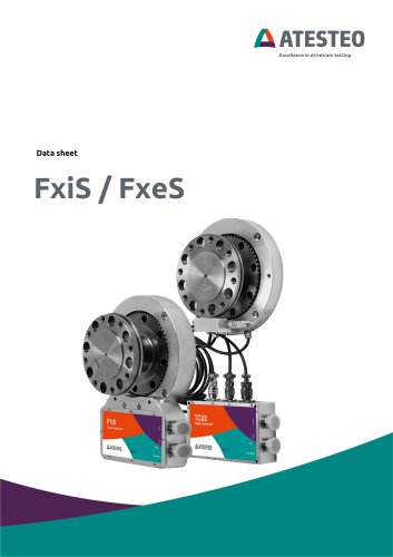 Data sheet F5xS
18 Pages
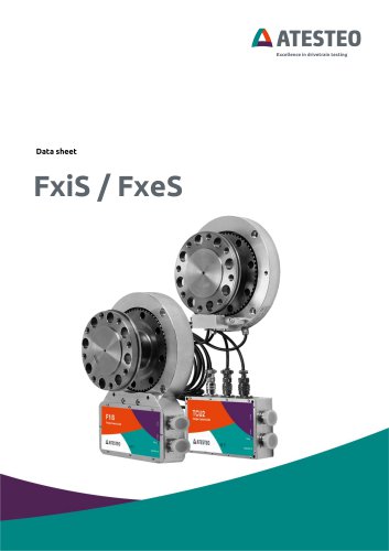 Data sheet F34xS
21 Pages
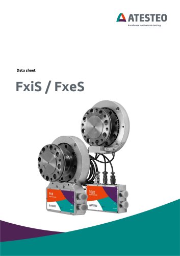 Data sheet F3xS
27 Pages
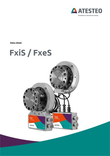 Data sheet F23xS
21 Pages
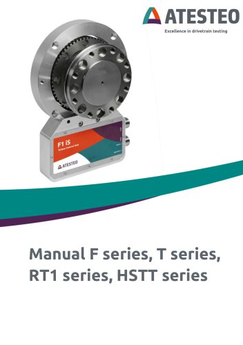 Manual Fx series
124 Pages
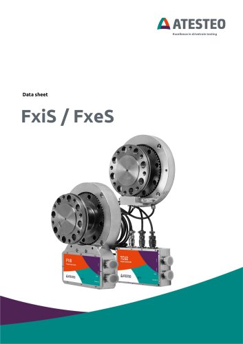 Data sheet F2xS
35 Pages
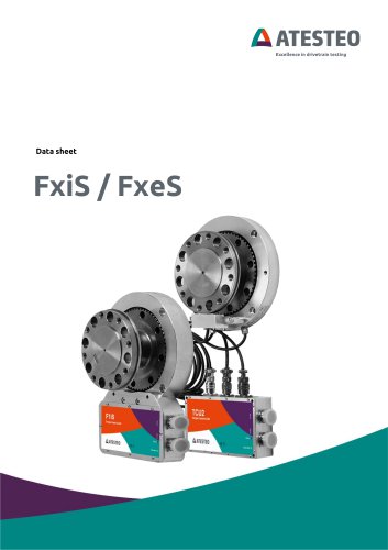 Data sheet F1xS
27 Pages
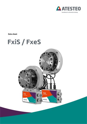 Data sheet F0xS
51 Pages
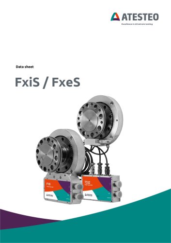 Data sheet F0xS-SV
27 Pages
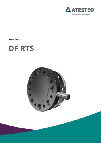 Data sheet DF RTS
11 Pages
 Data sheet DF plus HS
20 Pages
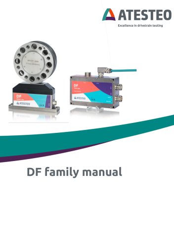 Manual DF plus series
132 Pages
 Data sheet DF plus series
41 Pages
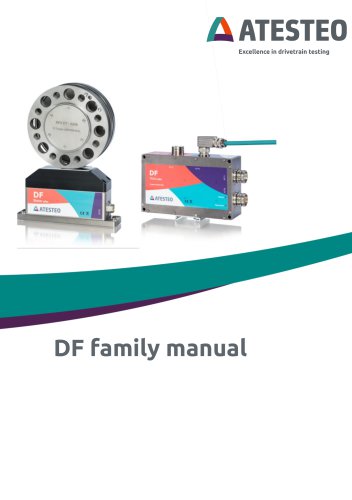 Manual DF dual series
132 Pages
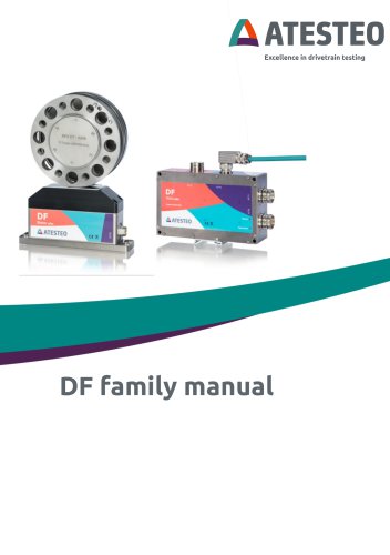 Manual DF ibex series
132 Pages
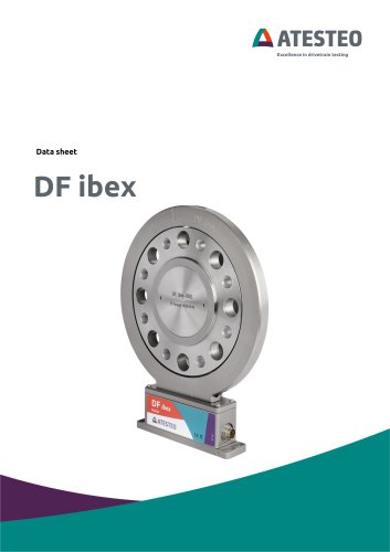 Data sheet DF3 ibex
21 Pages
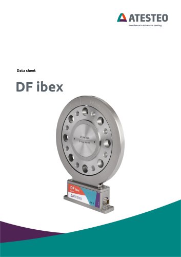 Data sheet DF2 ibex
21 Pages
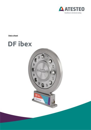 Data Sheet DF1 ibex
21 Pages

- ATESTEO torque sensor
- ATESTEO dynamic torque sensor
- ATESTEO rotary torque sensor
- ATESTEO analog torque sensor
- ATESTEO strain gauge torque sensor
- ATESTEO non-contact torque sensor
- ATESTEO digital torque sensor
- ATESTEO high-accuracy torque sensor
- ATESTEO DC torque sensor
- ATESTEO torque sensor with flange connection
- Compact torque sensor
- Modular temperature control
- ATESTEO voltage output torque sensor
- USB torque sensor
- 12VDC torque sensor
- Flange-mounted torque sensor
- ATESTEO test bench torque sensor
- ATESTEO torque sensor with integrated electronics
- Custom torque sensor
- Torque sensor with rotary encoder