
- Catalogs
- ATESTEO GmbH & Co. KG
- Manual DF ibex series

- Company
- Products
- Catalogs
- News & Trends
- Exhibitions
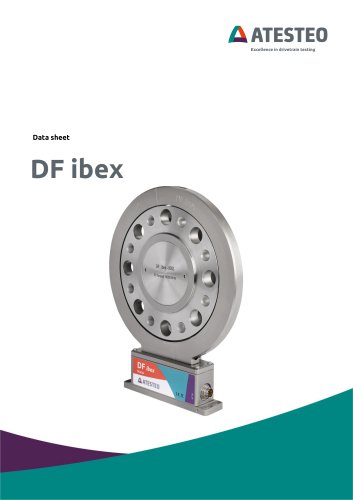
Manual DF ibex series
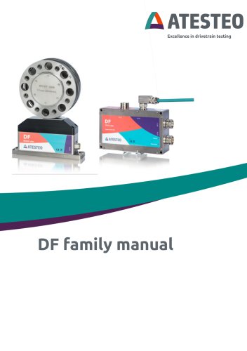
Manual DF ibex series
This manual offers detailed guidance for the ATESTEO DF series, covering variants such as DF plus, DF ibex, and DF dual. It stresses the importance of understanding safety instructions and potential hazards. The manual should accompany the DF series throughout its lifecycle.
Updates from versions 2.3 to 2.11 include FCC type label information, corrections to zero point offset descriptions, and updates to the CAN matrix and software.
General safety instructions, symbol explanations, appropriate use, and operator responsibilities are outlined. It also covers transport, storage, and safety notes for assembly and operation.
Technical data and system overviews are provided, including electrical, mechanical, and functional areas. Details on nameplates, calibration documents, telemetry, and measurement ranges are included.
Instructions for transporting, lifting, and mounting components like the rotor and stator are provided, along with grounding, wiring, and power/data cable connections.
Guidance on initial setup, including network connection and settings, proxy configuration, and using the web interface, is provided.
The web interface features are explained, including the home menu, system overview, power supply, alarm settings, and configuration options for torque meter, speed, rotation angle, and more.
Details on pin allocations for power supply, frequency output, analogue/CAN/alarm/input, Ethernet, and central cable connections are included.
Recommendations for zero adjustment, including considerations for thermal influences, hysteresis, aging, and lateral forces, are provided. The appendix also includes tables of figures and tables.
Tightening torques for various DF ibex and DF dual rotor models are outlined, with detailed specifications for each model.
Detailed instructions for mounting the DF plus stator and rotor, emphasizing grounding and alignment, are provided.
Tables specify nominal and tolerance distances for axial and radial displacement between the rotor and stator for different DF models.
An optional magnetic speed detection system is described, including alignment and maintaining a maximum radial distance of 1 mm from the magnetic ring.
The evaluation unit (TCU5) can be mounted on a DIN rail or metal plate, with proper grounding emphasized to prevent electromagnetic interference.
A point-to-point grounding concept is stressed to avoid electromagnetic interference, with recommendations for cable types and shielding to comply with EMC standards.
Before the first switch-on, ensure all components are correctly connected and aligned. LED indicators provide an overview of system states.
Use a common web browser such as Firefox, Chrome, Edge, or Safari, ensuring the latest version is installed.
To connect the TCU5 to an evaluation computer, use a CAT5-Patchcable and an RJ35-connection. Three connection options are available.
If not connected to a domain, adjust network settings with a specific IP address and subnet mask.
Add a new exception for the proxy system for a specific address space.
Access the web interface using a specific web address or IP address. The interface is only available in English.
Features include login, home menu, graph overview, system overview, power supply, alarm settings, torque meter, speed, rotation angle, analog settings, frequency settings, filter settings, and CAN settings.
CAN messages can be formatted in Intel or Motorola formats, with up to four messages configurable. Busload management is crucial for reliable transmission.
Several signals are available for debugging, with error counters indicating transmission errors.
CAN command messages can be configured for various commands, with responses sent upon successful receipt.
The status word uses all 8 bytes of a CAN message, representing different system states.
Improper Ethernet settings can damage the device, requiring factory reprogramming.
Initial access requires a username and password, with specific password requirements.
Firmware version and manufacturer contact details are available on the service page.
Details are provided for pin allocations on connectors, crucial for avoiding damage and ensuring correct operation.
Analog outputs for speed and rotation angle are configured via a web interface, with alarms triggered when thresholds are exceeded.
Pin functions depend on the firmware version, with specific functions defined in the web interface.
Details on Ethernet and central cable connections are provided, with specific pin allocations for power supply and data transmission.
Guidelines for zero-reset procedures are provided, emphasizing that zero-reset should only be performed when the torque is zero.
Numerous figures and tables detail system overviews, pin allocations, and technical data.
Contact details for ATESTEO GmbH & Co. KG are provided for further information or service requests.
Catalog excerpts
Excellence in drivetrain testing
Open the catalog to page 1
Your contact for service requests ATESTEO GmbH & Co. KG Konrad-Zuse-Str. 3 52477 Alsdorf Germany DF family manual - Version 2.11
Open the catalog to page 2
1.6 RSS-GEN — GENERAL REQUIREMENTS FOR COMPLIANCE OF RADIO DF family manual - Version 2.11
Open the catalog to page 3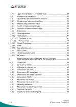
DF family manual - Version 2.11
Open the catalog to page 4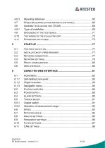
DF family manual - Version 2.11
Open the catalog to page 5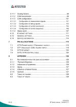
DF family manual - Version 2.11
Open the catalog to page 6
Thank you for choosing an ATESTEO quality product. Please read the system description carefully so you make the most of the versatile features of your product. This operating manual is a component of the DF-series and should always be carefully kept with the DF series until it is disposed of. It is impossible to eliminate every danger to people or material that the DF series might present. For this reason, every person working at the DF series or is involved in its transport, setting up, control, maintenance or repair must be properly instructed and be informed of the possible dangers. For this...
Open the catalog to page 7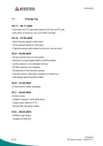
AATESTEO Introduction AATESTEO Introduction • Information for FCC type label added for DF ibex and DF dual • Description of maximum zero point offset corrected • Rotor firmware added to CAN matrix • TCU5 software added to CAN matrix • Tightening torque table cleaned up into plus, ibex and dual • Product variants ibex and dual added • Remark to connect Digital GND for CAN bus added • Central cable pin count mistakes removed • IIR filter explained more detailed • Screenshots of web interface updated • Fail safe channel: Description updated and cleaned up • CAN debug signal description added • Format...
Open the catalog to page 8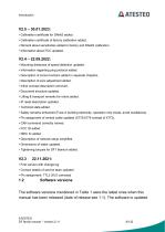
Introduction AATESTEO • Calibration certificate for DAkkS added. • Calibration certificate of factory calibration added. • Remark about sensitivities added to factory and DAkkS calibration. • Information about FCC updated. • Mounting distances of speed detection updated. • Information regarding ping protocol added. • Description of some functions added in separate chapters. • Description of zero adjustment added. • Inline concept description removed. • Document structure updated. • Lifting & transport remarks for rotors added. • IP reset description updated. • Technical data added. • Safety remarks...
Open the catalog to page 9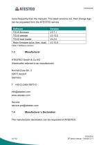
more frequently than the manuals. The latest versions incl. their change logs can be requested from the ATESTEO service. Table 1 Software versions ATESTEO GmbH & Co.KG (Hereinafter referred to as manufacturer) Konrad-Zuse-Str. 3 52477 Alsdorf Germany The manufacturer declaration can be requested at ATESTEO. DF family manual - Version 2.11
Open the catalog to page 10
The components of DF series mentioned in Table 2 comply with part 15 of the FCC Rules. Operation is subject to the following two conditions: (1) This device may not cause harmful interference, and (2) this device must accept any interference received, including interference that may cause undesired operation. Product changes are only allowed with the acceptance of ATESTEO. The FCC ID or a unique component ID is labelled on the components (see 3.6 and 3.7). This device contains licence-exempt transmitter(s)/receiver(s) that comply with Innovation, Science and Economic Development Canada’s licence-exempt...
Open the catalog to page 11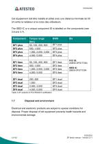
AATESTEO Cet equipement doit etre installe et utilise avec une distance minimale de 50 cm entre le radiateur et le corps des utilisateurs. The ISED IC or a unique component ID is labelled on the components (see 3.6 and 3.7). Table 2 DF variants of FCC/RSS210 certification Electrical and electronic products are subject to special conditions for disposal. Proper disposal of old equipment prevents health hazards and environmental damage. DF family manual - Version 2.11
Open the catalog to page 12
The original packaging of ATESTEO equipment can be recycled, as it is made of recyclable material. However, you should keep the packaging for at least the warranty period. In the event of a complaint, the torque flange, as well as the accessories, must be returned in the original packaging. Due to ecological aspects, the return of the empty packaging should be waived. Electrical and electronic devices bearing the symbol / are subject to the European Directive 2002/96 / EC on waste electrical and electronic equipment. The symbol indicates that waste equipment that is no longer usable must be disposed...
Open the catalog to page 13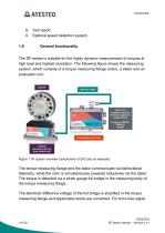
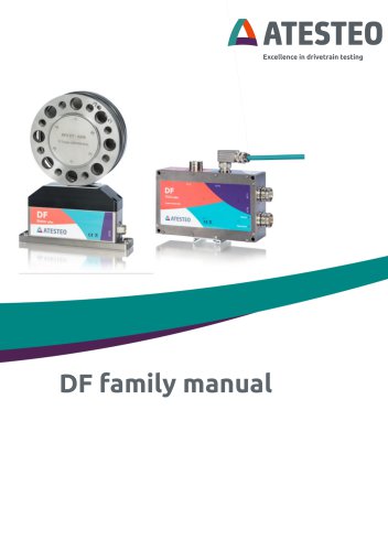
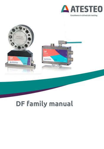
AATESTEO Introduction 9. Optional speed detection system The DF-series is suitable for the highly dynamic measurement of torques at high load and highest resolution. The following figure shows the measuring system, which consists of a torque measuring flange (rotor), a stator and an evaluation unit. CENTRAL CABLE X770 / X771 Customer interfaces for power supply and output signals ibex/dual: with ring plus: without ring Figure 1 DF system overview (components of DF2 plus as example) The torque measuring flange and the stator communicate via bidirectional telemetry, while the rotor is simultaneously...
Open the catalog to page 14
transmission, the data words are supplemented by a checksum and transmitted modulated to the stator. The stator demodulates the data words and transmits them via an RS422 interface to the evaluation unit. In the evaluation unit, the signals can additionally be filtered with an adjustable lowpass filter. The evaluation unit also offers the connection options for the system peripherals. These include a CAN interface, two frequency outputs (Md1, Md2), three galvanically isolated analog outputs (Md1, Md2, Speed), three digital alarm outputs and five digital inputs. The measuring system can be comfortable...
Open the catalog to page 15
offset by 90 ° to each other. So the speed can be determined as well as the direction of rotation. The two tracks can be tapped as RS422 signals at the system outputs. In addition, the speed is measured in the evaluation unit and made available as a digital value via CAN and as a voltage value via the third analog output. Note Please note that the torque meter is a high-precision measuring instrument. Mechanical effects, e.g. hammer impacts, lead to deformation of the measuring body, which changes its torsional behavior and thus worsens the measuring accuracy! Before mounting, make sure that...
Open the catalog to page 16All ATESTEO GmbH & Co. KG catalogs and technical brochures
 Data sheet F6xS
21 Pages
 Manual PTO series
14 Pages
 Data sheet PTO series
14 Pages
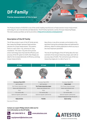 Flyer DF-family
4 Pages
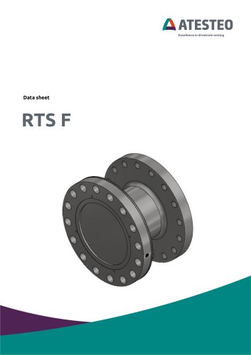 Data sheet F4 RTS
7 Pages
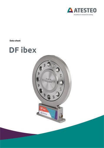 Data sheet DF4 ibex
21 Pages
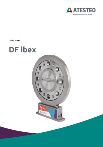 Data sheet DF5 ibex
21 Pages
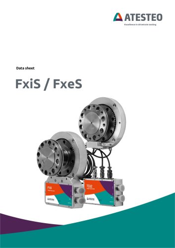 Data sheet F4xS
21 Pages
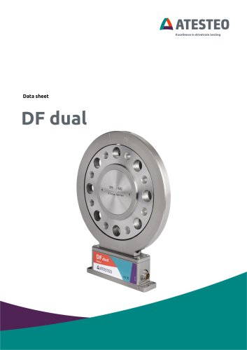 Data sheet DF5 dual
23 Pages
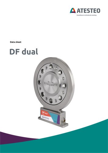 Data sheet DF4 dual
23 Pages
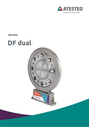 Data sheet DF3 dual
23 Pages
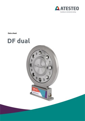 Data sheet DF2 dual
23 Pages
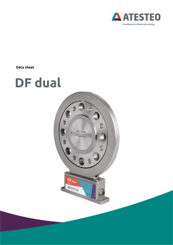 Data sheet DF1 dual
23 Pages
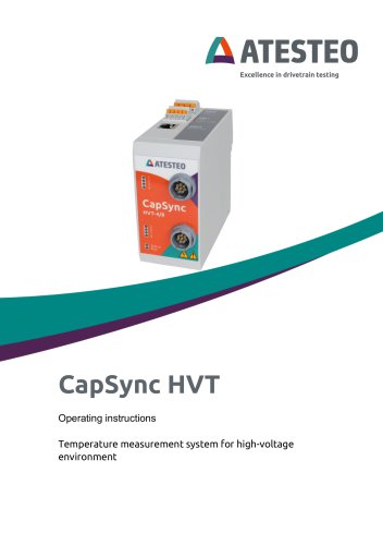 Manual CapSync HVT
68 Pages
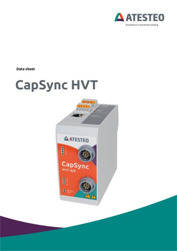 Data sheet CapSync HVT
7 Pages
 Manual IRTS series
116 Pages
 Data sheet IRTS-P
11 Pages
 Manual VETAS 3
30 Pages
 Manual VECTO
26 Pages
 Manual steering wheel
17 Pages
 Data sheet steering wheel
9 Pages
 Manual DST series
69 Pages
 Data sheet DST series
13 Pages
 Data sheet TiS Z50
20 Pages
 Manual T series
124 Pages
 Data sheet TeS Z50
21 Pages
 Manual RT11 series
124 Pages
 Data sheet RT11eS-B
20 Pages
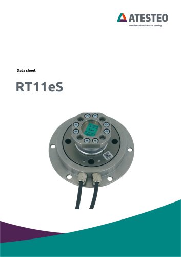 Data sheet RT11eS
17 Pages
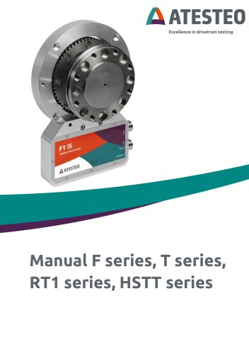 Manual HSTTeS series
124 Pages
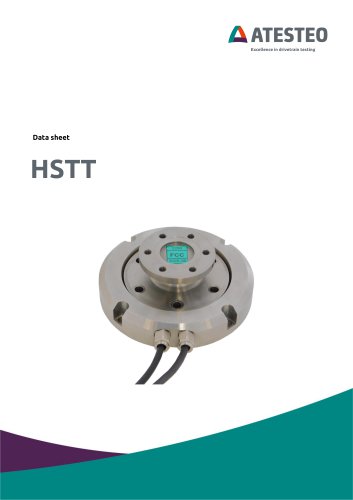 Data sheet HSTTeS series
20 Pages
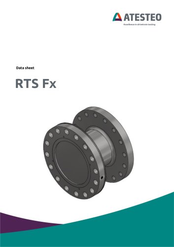 Data sheet F23 RTS
7 Pages
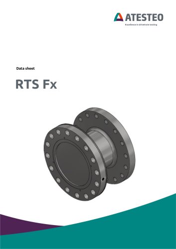 Data sheet F3 RTS
7 Pages
 Data sheet F5xS
18 Pages
 Data sheet F34xS
21 Pages
 Data sheet F3xS
27 Pages
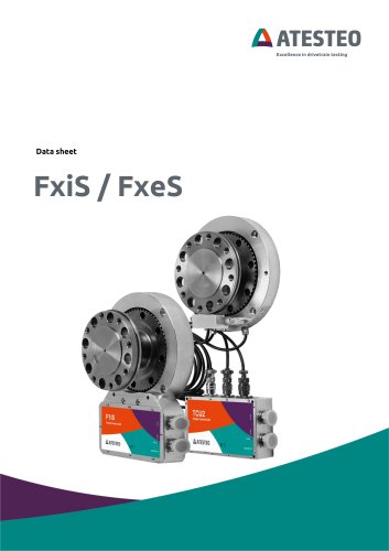 Data sheet F23xS
21 Pages
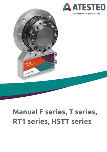 Manual Fx series
124 Pages
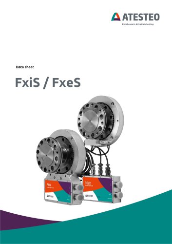 Data sheet F2xS
35 Pages
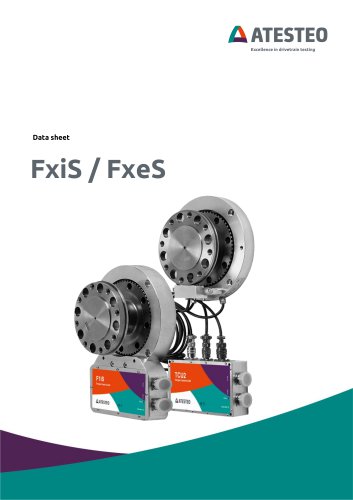 Data sheet F1xS
27 Pages
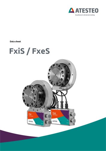 Data sheet F0xS
51 Pages
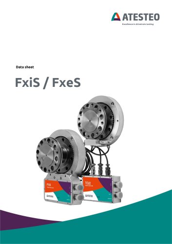 Data sheet F0xS-SV
27 Pages
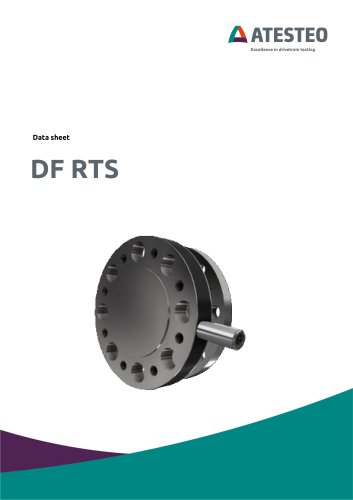 Data sheet DF RTS
11 Pages
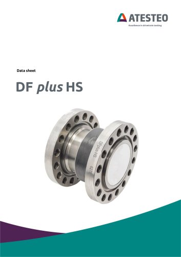 Data sheet DF plus HS
20 Pages
 Manual DF plus series
132 Pages
 Data sheet DF plus series
41 Pages
 Manual DF dual series
132 Pages
 Data sheet DF3 ibex
21 Pages
 Data sheet DF2 ibex
21 Pages
 Data Sheet DF1 ibex
21 Pages

- ATESTEO torque sensor
- ATESTEO dynamic torque sensor
- ATESTEO rotary torque sensor
- ATESTEO analog torque sensor
- ATESTEO strain gauge torque sensor
- ATESTEO non-contact torque sensor
- ATESTEO digital torque sensor
- ATESTEO high-accuracy torque sensor
- ATESTEO DC torque sensor
- ATESTEO torque sensor with flange connection
- Modular temperature control
- Compact torque sensor
- ATESTEO voltage output torque sensor
- USB torque sensor
- 12VDC torque sensor
- Flange-mounted torque sensor
- ATESTEO test bench torque sensor
- ATESTEO torque sensor with integrated electronics
- Custom torque sensor
- Torque sensor with rotary encoder