
- Catalogs
- ATESTEO GmbH & Co. KG
- Manual DF ibex series

- Company
- Products
- Catalogs
- News & Trends
- Exhibitions
Manual DF ibex series
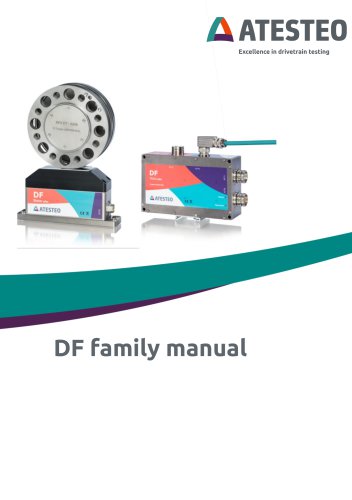
Manual DF ibex series
The manual provides guidance for the ATESTEO DF series, including variants DF plus, DF ibex, and DF dual. It stresses the importance of safety instructions and notes the manufacturer's right to make technical changes without documentation.
Updates from versions 2.3 to 2.9 include new product variants, improved CAN bus connections, and updates to the web interface and safety channel descriptions.
Lists the latest software versions for components like TCU5 and rotor firmware, indicating frequent software updates.
Contact details for ATESTEO GmbH & Co. KG are provided for further assistance.
Confirms compliance with FCC Rules for DF series components under specific conditions.
Emphasizes adherence to safety instructions, covering general safety, transport, storage, and assembly notes.
Includes technical data and system overviews, covering electrical, mechanical, and functional areas, calibration documents, and telemetry measurement ranges.
Guides on transporting, lifting, and mounting components, including dimensions and grounding instructions.
Instructions for initial setup, network configuration, and using the web interface for system management.
Details pin allocations for power supply, frequency output, and other connections.
Includes recommendations for zero adjustment and tables for reference.
Outlines compliance requirements under FCC and ISED regulations, including labeling requirements.
Devices should be installed 50 cm from users, with proper installation emphasized for accurate measurements.
Electrical products must be disposed of according to regulations, with recyclable packaging.
The DF-series is designed for dynamic torque measurement, using telemetry for communication and offering various interfaces.
Provides detailed specifications, including power supply, temperature ranges, and protection class.
Details the system's functional, mechanical, and location aspects, including component descriptions and label positioning.
Includes a test report indicating sensitivity, with optional calibration protocols available.
Outlines single and dual range telemetry options and the procedure for switching measurement ranges.
Includes zero adjustment, test signals, IP address reset, filtering, and a fail-safe channel for overload analysis.
Covers transport, lifting, and mounting procedures, with guidelines for alignment and grounding.
Specific instructions for mounting the rotor and stator, including torque wrenches and component positioning.
An optional magnetic speed detection system is available, with factory-set nominal distance and adjustable settings.
Should be installed in a dry environment, with specific temperature and humidity conditions.
A point-to-point grounding concept is recommended to avoid electromagnetic interference.
Specifies device plugs for connection to peripherals and the Ethernet interface, with shielded cables recommended.
Ensure all components are correctly connected before initial switch-on, with LEDs indicating operating status.
Used for system configuration, requiring a password for login and providing a graph overview of signals.
Guidance on using the web interface for monitoring and controlling torque sensors.
Torque, acceleration, speed, and temperature inputs are graphically represented, though not in real-time.
Transmission status and alarm states are indicated, with adjustable alarm limits.
The supply voltage is adjustable, affecting signal quality, with critical values deactivating the power supply.
Settings are changeable in the settings menu, with analogue output channels listed.
Parameters are shown, with manual value definition possible.
Voltage range of analog outputs is adjustable, with calibration recommended for trained personnel only.
The TCU provides a digital IIR filter, with configurable CAN interface and scaling factors.
CAN messages can be configured, with debug signals available for monitoring errors.
Proper values are crucial to avoid measurement errors or device damage.
Outlines the CAN command list and response message structure.
Uses all 8 bytes of a CAN message, with a detailed table of bit functions.
Instructions for configuring Ethernet settings, with warnings about improper settings.
Initial access credentials and password guidelines are provided.
Includes firmware version and manufacturer contact information.
Detailed pin allocation for connectors, including signal descriptions and cable specifications.
Represents torque and speed tracks, with warnings against connecting outputs to ground.
Step-by-step procedure for resetting the IP configuration to factory settings.
Allows digital data reception and control signal transmission, with configuration details provided.
Indicate threshold exceedance, with reset procedures and configuration options.
Outlines specifications for double telemetry systems and digital rotor data transmission.
Highlights factors affecting zero drift and emphasizes proper maintenance.
Zero drift due to temperature fluctuations is specified.
Drift due to sensor loading direction is explained.
Long-term dynamic loading effects are discussed.
Influence from linked components is minimized by proper installation.
Zero-reset is advised only when the real load is zero.
Includes visual aids supporting the textual information.
Contact details for ATESTEO GmbH & Co. KG are provided for inquiries or service requests.
Catalog excerpts
Excellence in drivetrain testing
Open the catalog to page 1
Your contact for service requests ATESTEO GmbH & Co. KG Konrad-Zuse-Str. 3 52477 Alsdorf Germany ATESTEO DF family manual - Version 2.9
Open the catalog to page 2
1.6 RSS-Gen — General requirements for Compliance of Radio DF family manual - Version 2.9
Open the catalog to page 3
ATESTEO DF family manual - Version 2.9
Open the catalog to page 4
DF family manual - Version 2.9
Open the catalog to page 5
ATESTEO DF family manual - Version 2.9
Open the catalog to page 6
Thank you for choosing an ATESTEO quality product. Please read the system description carefully so you make the most of the versatile features of your product. This operating manual is a component of the DF-series and should always be carefully kept with the DF series until it is disposed of. It is impossible to eliminate every danger to people or material that the DF series might present. For this reason, every person working at the DF series or is involved in its transport, setting up, control, maintenance or repair must be properly instructed and be informed of the possible dangers. For this...
Open the catalog to page 7
AATESTEO kind of suggestion or criticism that you may wish to make. Please let us know or write to us. This will help us to make the operating instruction still more user-friendly in taking account of your wishes and requirements. • Product variants ibex and dual added • Remark to connect Digital GND for CAN bus added • Central cable pin count mistakes removed • 11R filter explained more detailed • Screenshots of web interface updated • Fail safe channel: Description updated and cleaned up • CAN debug signal description added • Format fixed for better readability • Format review • Update of drawing...
Open the catalog to page 8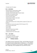
Introduction AATESTEO • Information about FCC updated. • Mounting distances of speed detection updated. • Information regarding ping protocol added. • Description of some functions added in separate chapters. • Description of zero adjustment added. • Inline concept description removed. • Document structure updated. • Lifting & transport remarks for rotors added. • IP reset description updated. • Technical data added. • Safety remarks enhanced (Fuse in building electricity, operation only inside, avoid oscillations). • Pin assignment of central cable updated (X775/X776 instead of X773). • CAN...
Open the catalog to page 9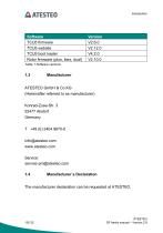
Table 1 Software versions 1.3 Manufacturer ATESTEO GmbH & Co.KG (Hereinafter referred to as manufacturer) Konrad-Zuse-Str. 3 52477 Alsdorf Germany The manufacturer declaration can be requested at ATESTEO. ATESTEO DF family manual - Version 2.9
Open the catalog to page 10
The components of DF series mentioned in Table 2 comply with part 15 of the FCC Rules. Operation is subject to the following two conditions: (1) This device may not cause harmful interference, and (2) this device must accept any interference received, including interference that may cause undesired operation. Product changes are only allowed with the acceptance of ATESTEO. The FCC ID or a unique component ID is labelled on the components (see 3.6 and 3.7). This device contains licence-exempt transmitter(s)/receiver(s) that comply with Innovation, Science and Economic Development Canada’s licence-exempt...
Open the catalog to page 11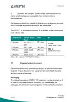
2. L’appareil doit accepter tout brouillage radioelectrique subi, meme si le brouillage est susceptible d’en compromettre le fonctionnement Cet equipement doit etre installe et utilise avec une distance minimale de 50 cm entre le radiateur et le corps des utilisateurs. The ISED IC or a unique component ID is labelled on the components (see 3.6 and 3.7). Table 2 DF variants of FCC/RSS210 certification Electrical and electronic products are subject to special conditions for disposal. Proper disposal of old equipment prevents health hazards and environmental damage. The original packaging of ATESTEO...
Open the catalog to page 12
Introduction AATESTEO the torque flange, as well as the accessories, must be returned in the original packaging. Due to ecological aspects, the return of the empty packaging should be waived. Electrical and electronic devices bearing the symbol / ^'i'\ are subject to the European Directive 2002/96 / EC on waste electrical and electronic equipment. The symbol indicates that waste equipment that is no longer usable must be disposed of separately from regular household waste in accordance with European environmental protection and recycling regulations. However, the disposal regulations vary from...
Open the catalog to page 13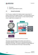
AATESTEO Introduction 9. Optional speed detection system The DF-series is suitable for the highly dynamic measurement of torques at high load and highest resolution. The following figure shows the measuring system, which consists of a torque measuring flange (rotor), a stator and an evaluation unit. CENTRAL CABLE X770 / X771 Customer interfaces for power supply and output signals ibex/dual: with ring plus: without ring Figure 1 DF system overview (components of DF2 plus as example) The torque measuring flange and the stator communicate via bidirectional telemetry, while the rotor is simultaneously...
Open the catalog to page 14
The electrical difference voltage of the full bridge is amplified in the torque measuring flange and digital data words are converted. For error-free signal transmission, the data words are supplemented by a checksum and transmitted modulated to the stator. The stator demodulates the data words and transmits them via an RS422 interface to the evaluation unit. In the evaluation unit, the signals can additionally be filtered with an adjustable low-pass filter. The evaluation unit also offers the connection options for the system peripherals. These include a CAN interface, two frequency outputs...
Open the catalog to page 15
sent from the measuring flange, which enables automatic configuration of the evaluation unit. The new measuring flange is immediately ready for use. Optionally, the measuring system can be equipped with a speed measurement. For the capture, a magnet ring on the rotor and a sensor head on the stator are in use. The magnetic ring has two pole tracks, which are offset by 90 ° to each other. So the speed can be determined as well as the direction of rotation. The two tracks can be tapped as RS422 signals at the system outputs. In addition, the speed is measured in the evaluation unit and made available...
Open the catalog to page 16All ATESTEO GmbH & Co. KG catalogs and technical brochures
 Flyer DF-family
4 Pages
 Data sheet F4 RTS
7 Pages
 Data sheet DF4 ibex
21 Pages
 Data sheet DF5 ibex
21 Pages
 Data sheet F4xS
21 Pages
 Data sheet DF5 dual
23 Pages
 Data sheet DF4 dual
23 Pages
 Data sheet DF3 dual
23 Pages
 Data sheet DF2 dual
23 Pages
 Data sheet DF1 dual
23 Pages
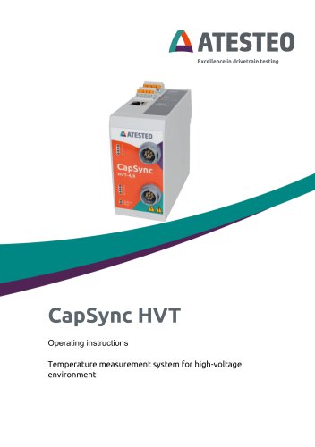 Manual CapSync HVT
68 Pages
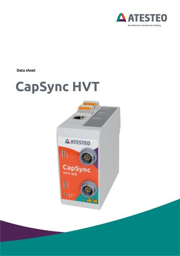 Data sheet CapSync HVT
7 Pages
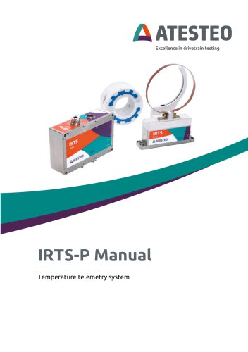 Manual IRTS series
116 Pages
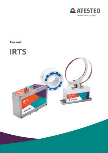 Data sheet IRTS-P
11 Pages
 Manual VETAS 3
30 Pages
 Manual VECTO
26 Pages
 Manual steering wheel
17 Pages
 Data sheet steering wheel
9 Pages
 Manual DST series
69 Pages
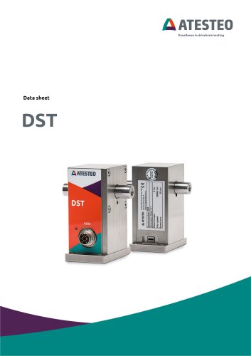 Data sheet DST series
13 Pages
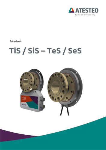 Data sheet TiS Z50
20 Pages
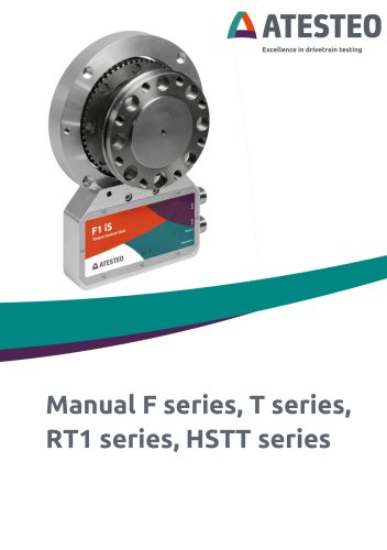 Manual T series
124 Pages
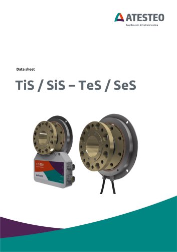 Data sheet TeS Z50
21 Pages
 Manual RT11 series
124 Pages
 Data sheet RT11eS-B
20 Pages
 Data sheet RT11eS
17 Pages
 Manual HSTTeS series
124 Pages
 Data sheet HSTTeS series
20 Pages
 Data sheet F23 RTS
7 Pages
 Data sheet F3 RTS
7 Pages
 Data sheet F5xS
18 Pages
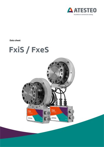 Data sheet F34xS
21 Pages
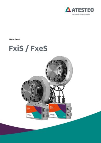 Data sheet F3xS
27 Pages
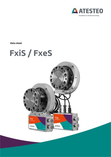 Data sheet F23xS
21 Pages
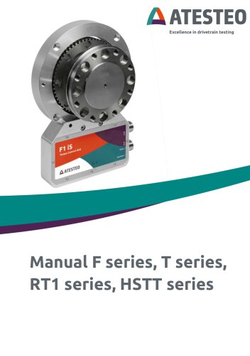 Manual Fx series
124 Pages
 Data sheet F2xS
35 Pages
 Data sheet F1xS
27 Pages
 Data sheet F0xS
51 Pages
 Data sheet F0xS-SV
27 Pages
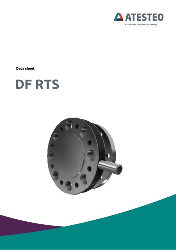 Data sheet DF RTS
11 Pages
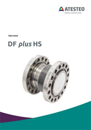 Data sheet DF plus HS
20 Pages
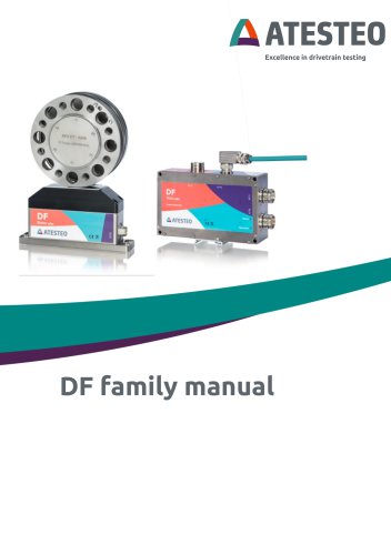 Manual DF plus series
132 Pages
 Data sheet DF plus series
41 Pages
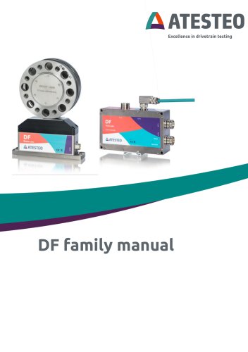 Manual DF dual series
132 Pages
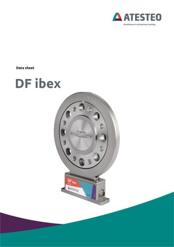 Data sheet DF3 ibex
21 Pages
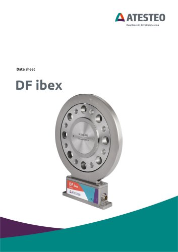 Data sheet DF2 ibex
21 Pages
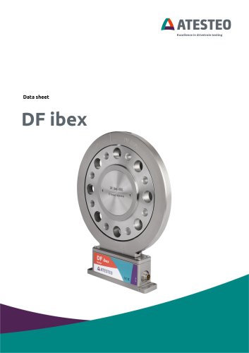 Data Sheet DF1 ibex
21 Pages

- ATESTEO dynamic torque sensor
- ATESTEO rotary torque sensor
- ATESTEO analog torque sensor
- ATESTEO strain gauge torque sensor
- ATESTEO non-contact torque sensor
- ATESTEO digital torque sensor
- ATESTEO high-accuracy torque sensor
- ATESTEO DC torque sensor
- ATESTEO torque sensor with flange connection
- Compact torque sensor
- Modular temperature control
- ATESTEO voltage output torque sensor
- USB torque sensor
- 12VDC torque sensor
- Flange-mounted torque sensor
- ATESTEO test bench torque sensor
- ATESTEO torque sensor with integrated electronics
- Custom torque sensor
- Torque sensor with rotary encoder