- Catalogs
- ATC PRODUCTION
- ENIGNEERED SOLUTIONS FOR ELECTRIFIED SYSTEMS
ENIGNEERED SOLUTIONS FOR ELECTRIFIED SYSTEMS
1 /79Pages

ENIGNEERED SOLUTIONS FOR ELECTRIFIED SYSTEMS
1 /79Pages
Catalog excerpts
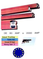
Insul Trolley
Open the catalog to page 2
RAILS CONDUCTEURS GAINES Les rails son! fournls en longueur standard avec le dispositil do connexion, la qaine isolante et le couvre* joints. Tension maximale d'uliilsdllon : 600 V. Nolo ■ LM grille* de nutpeniion doivent elm command*** atiparO menl • Pour It- rail i*n cuivre plain de 500 A IM ACIIMM doivenl *lr« mmmand^ot sfrparement • L'outil do montage e«t loumi graoeuwrmnl (rails auembWi par bfochwi RAILS CINTRES : A la i.'ommande il laul preciser la reference ci dessus, la longueur exacte el le rayon de courbure. L>ux portions droiles de 300 mm doivent etre prevues a ehaque -^xtremite de...
Open the catalog to page 3
INSUL 8 BAR CAPTEURS DE COURANT • 60 amperes et 2X60 amperes (lignes droites exclusivement).
Open the catalog to page 5
INSUL 8 BAR ACCESSOIRES DE LIGNE alimentation electrique par contacts glissants
Open the catalog to page 6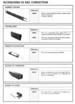
ACCESSOIRES DU RAIL CONDUCTEUR
Open the catalog to page 7
ACCESSOIRES DU RAIL CONDUCTEUR
Open the catalog to page 9
AGRAFES DE SUSPENSION ET DE RACCORDEMENT POUR CONDUCTEUR RAINURE Dans les agrafes do raccordement, serrer alternativement les vis, pour eviter de rejeter ie fil conducteur. Terminal male double conducteur AGRAFES DE SUSPENSION ET RACCORD POUR CONDUCTEUR CYLINDRIQUE Relerence a"^"" Lo^*u' FUOaoe
Open the catalog to page 10
TECHNICAL DATA HE VI BAR 3 pioleclod conducloi bors moel (he demands of ihc following international safety standards Conductor Bar cover Standard Medium heat Volume resistivity >10,,l)/an >IO'«U/an V.cat sohening temperature 85* C 125' C Self extinguishing Self extinguishing Ciau sectional area 3 18 mm' Nominal voliage Minimum pitrh centres between conductors 50 mm F'panMor sections Aluminium ♦ Stainless steel MM£NSIONING AND CHOICE OF CONDUCTORS An accurate choice ol conductor* con only be made when the folio It. type ul cui.eni s>ngle u 3 phase AC . ...-,...„.., (DC) The ma-imum ( unenl and...
Open the catalog to page 13
INSULATED CONDUCTOR BAR - 6 m LONG Pott N" Phose covet standord Part N" Earlh cover standard Port N Medium heal covei The oluminium conductor profile ■ gives vertical and horizontal rigidity, and its large surface area ensures efficient heal dissipation A stainless steel slnp 2 is crimped into the conductor to provide a longJastmg contact surface PVC or Bayblend cover -i provides a degree of protection in accordance with the required safety standards Ihe cover is shaped to shed water EXPANSION SECTION - 6 m LONG Part N Phase cover standord Part N'' Earth cover standard Pari N Medium heal cover...
Open the catalog to page 14
POWER FEED An aluminium powerfeed |Oinl i, clomped onto the top hall ol the bars, allows connection lor Each powerleed |Oinl is protected by a joint cover 2) and ends caps 3 which have grommets adjustable • to the diametre or the feed coble
Open the catalog to page 15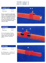
Bars are supported by single hanger clamps i , made ol isolating material, which con be clamped onto any point of the line A central bolt 2' ensures a 360" rotation and allows expansion. The pitch centre between bars is 50 mm The support pilch between hanger To anchot the system, anchoring clips i are placed either side ol a hanger clamp, in the middle of the system or between 2 expansion An insulating cover • pushed on to
Open the catalog to page 16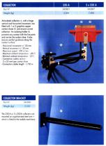
Articulated collectors with a lorge vertical and horizontal movement, are fitted with I or 2 graphite copper contact shoes f, and ensure current collection. An isolating holder 3', prevents any contact with the live parts and carries the carbon shoe. It also ensures perfect guidance along the contact surface - Maximum ambient tempeiolure ♦ 80 C -Minimum ambient lempetoluie 20 C - Connection cables section ■ Connection cables length 1.700 m COLLECTOR BRACKET mounted on a galvanized steel arm i which is fitted to the mobile machiner
Open the catalog to page 17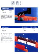
SUPPORT BRACKET A galvanized steel support bracket i. to be welded on lo a steel support This will carry 4 hanger clamps al ISOLATING JOINT The isolating joint I is identical in shape and has the same features as the standard joinl It provides a adjoining bars by means of an air Each isolating joint is protected by a joinl cover J and end caps '
Open the catalog to page 18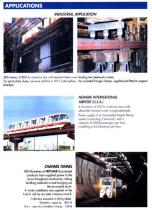
INDUSTRIAL APPLICATION 300 metres of 800 A condix lot boi wiib medium heat covet feeding Iwo steelwork crones. For particularly dusty, corrosive and hot [* 80 C| atmosphere Use insulated hanger clamps, supplied pre-fitted to support NEWARK INTERNATIONAL 4 kilometres ol 900 A conducloi bars with ultraviolet resistant cover in polycarbonate Power supply of an Automated People Mover system connecting 3 terminals, with a capacity ol 2600 passengers per hour, travelling at 45 kilometres per hour CHANNEL TUNNEL 180 kilometres of HBVI-BAR 3 protected conductor bars supplied power to the locos throughout...
Open the catalog to page 19
LIDNES ELECTRIQUES
Open the catalog to page 20
DONNEES PREALABLES V ■ Tension d'alimenlation en Volts. 0 - Position el nombre d'alimenlations. Au - Chute maximum de tension admise. ED • Facteur de fonctionnement (normalement entre 40 et 100%). a - Distance entre rails. CALCUL D'INTENSITE Pour un contrdle sans une grande precision, on peut utiliser le graphique 4 comme complement de calcul. La section sera calculee au moyen des graphiques 1 et 2, en fonction du tacteur de fonctionnement. En raison de secunte. si on ignore le ED de travail, prendre le plus grand estime. La valeur maximum correspond a 100% et le minimum a 40%. STABILITE THERMIOUE...
Open the catalog to page 22
L'impedance se calcule a I'aide du graphique 3 l(ED)=lnlensite correspondant au facteur de lonclionnemenl= Z=lmpedance calculee sur graphique 3 Alimentation par les deux extremites = —7- Alimentation —r- a chaque extremite - La valeur L est reduite, par rapport a la largeur des machines mobiles. Au(%) =--- Elle determine pourcentage calcule Si le % de chute de tension calcule etait superieur au pourcentage souhaite, refalre les calculs avec les variantes 1. Augmenter la section du cuivre 2. Diminuer la distance entre les conducteurs 3. Augmenter les branchements en dimlnuant L (le mode le plus...
Open the catalog to page 23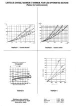
LIMITES DE CHARGE, MAXIMUM ET MINIMUM, POUR LES DIFFERENTES SECTIONS utilises normalement sur lignc alimentation rigide
Open the catalog to page 24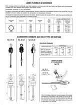
LIGNES FLEXIBLES D'ADHERENCE Pour montage vertical at horizontal, avec des matenaux communs pour les deux types, ces lignes sont economiques. Umitees pour des vilesses allant jusqu a 120 metres minute. Conducteur maximum 11 mm. de diametre On tend le conducteur par palan en approchement. Tension finale avec les isolateurs tenseurs des extremites Ne pas depasser 1/3 de la valeur de cassure du conducteur en temperature minimum. Les supports d'appui se placent entre 5 et 10 metres. Monler la prise de courant. 25 mm plus haut que le centre teon- que du conducteur, pour permeltre un contact correct....
Open the catalog to page 25All ATC PRODUCTION catalogs and technical brochures
 ELECTRIC PEDAL CONTROL
6 Pages

- Electrical rotary joint
- Hose reel
- Retractable reel
- Hoist
- Nora weight indicator
- Metal slip ring
- Hollow-shaft electrical slip ring
- Limit switch
- Chain hoist
- Electric electrical rotary joint
- Contactor
- Compact electrical rotary joint
- IP54 slip ring
- Overload clutch
- Capsule slip ring
- LED display weighing terminal
- Cable hoist
- Water reel
- Electric chain hoist
- Electric cable hoist