1260-75
1 /2Pages

1260-75
1 /2Pages
Catalog excerpts
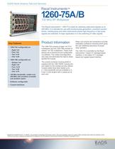
EADS North America Test and Services Racal Instruments™ 1260-75A/B 100 MHz RF Multiplexer The Racal Instruments™ 1260-75 is ideal for switching wide-band signals up to 200 MHz. It is intended for use with function/pulse generators, universal counter/ timers, oscilloscopes and other instruments where high frequency or fast pulse signals are switched. A major application is in the switching of video signals. Key Features • 1260-75A configurable as: ––Eight 1x4 ––Four 1x9 ––Two 1x19 ––One 1x39 • 1260-75B configurable as: ––Sixteen 1x4 ––Eight 1x9 ––Four 1x19 ––Two 1x39 ––One 1x79 • 100 Mhz bandwidth, usable over 200 MHz with excellent crosstalk and isolation specs Product Information The 1260-75A consists of eight 1x4 75 Ω multiplexers and the 1260-75B consists of sixteen 1x4 75Ω multiplexers. These multiplexers are bi-directional and configurable via software. This makes reconfiguration very easy and eliminates the need to disassemble the module. Relay coil currents are monitored to provide selectable confidence checking which gives the user additional assurance of proper relay operation. The 1260-75 is controlled by the Racal Instruments™ Option 01 message-based interface, or the Option 01T messagebased and register-based interface. The coaxial connector housing (shell) is supplied with the 1260 75A/B. Coaxial pins and cables for this module are also offered. Coaxial cables have been tested up to a 1 GHz bandwidth and are available in 2, 6 and 12 foot lengths with a coaxial pin at each end. • Software configurable • Coaxial interfaces ECO# 2011-EADSTS-02-01-11-38-MU. Uncontrolled Unclassified Information (“UUI”). This documentation does not contain ITAR-controlled data within the definition of the ITAR and has been reviewed and approved for release to non-US persons. EADS North America Proprietary Copyright © 2011
Open the catalog to page 1
EADS North America Test and Services Note: The EADS North America Test and Services policy is one of continuous develop- ment and improvement. Consequently, the equipment may vary in detail from the descrip- tion and specifications in this publication. Maximum Switchable Voltage (Signal-Signal Ground, Resistive Load) Maximum Switchable Current Per Maximum Carry Current Maximum Switchable Power Per Chan- Path Resistance Insulation Resistance Rise/Fall Time (Typical) Propagation Delay Time (Typical) Power Requirements User Connector: GMCT • Crimp Shielded Contact from Positron- ics Industries,...
Open the catalog to page 2All Astronics Test Systems catalogs and technical brochures
 1264c
1264c2 Pages
 4024h
4024h1 Page
 Option 01T
2 Pages
 1256L
1256L2 Pages
 1260-101
2 Pages
 1260-100
2 Pages
 1260-152/172
3 Pages
 1260-120
3 Pages
 1260-150
3 Pages
 1260-136B/C/D
2 Pages
 1260-138A
3 Pages
 1260-134
2 Pages
 1260-167AH/BH
2 Pages
 1260-164AH/BH
2 Pages
 1260-162AH/BH
2 Pages
 1260-145A-G
3 Pages
 1260-116
2 Pages
 1260-117/117A
3 Pages
 1260-118/118A
3 Pages
 3172
31726 Pages
 3152B
3152B6 Pages
 3151B
3151B5 Pages
 3164_2_0
3 Pages
 3156c
3156c5 Pages
 313A
313A1 Page
 6084A-104-DMM
5 Pages
 6084-2105
2 Pages
 PXIe-1803
4 Pages
 PXIe-6943
6 Pages
 VX407C
2 Pages
 VX405C
2 Pages
 203PC-1, 2
3 Pages
 1257A
1257A10 Pages
 1263HPf
2 Pages
 T940
T9408 Pages
 COTS Product Guide December, 2011
339 Pages
 1261B-S-2378
2 Pages
 1261B linear
3 Pages
 1261B
1261B5 Pages
 1260-x153
2 Pages
 1260-x121
2 Pages
 1260-1114
2 Pages
 1260-700
2 Pages
 1260-155
2 Pages
 1260-115
2 Pages
 1260-114
3 Pages
 1260-88
2 Pages
 1260-58
2 Pages
 1260-54
2 Pages
 1260-51
2 Pages
 1260-16
2 Pages
 1260-14
2 Pages
 1260-00C
3 Pages
 1255A
1255A2 Pages


- LIMING management software
- Data logger
- LIMING digital I/O
- LIMING Windows software
- Calibration system
- Temperature datalogger
- LIMING signal amplifier
- Simulation software solution
- Wireless datalogger
- Automated software
- Transceiver module
- LIMING automatic testing device
- Datalogger without display
- Development software
- Multimeter
- Portable calibrator
- Digital multimeter
- Temperature calibration system
- Engineering software
- Test set