1260-51
1 /2Pages

1260-51
1 /2Pages
Catalog excerpts

EADS North America Test and Services Racal Instruments™ 1260-51 400 MHz RF Matrix The Racal Instruments™ 1260-51 is ideal for high performance RF switching. Its 400MHz bandwidth makes the 1260-51 an excellent switch module for mediumspeed digital, datacomm and most analog signals. Key Features • Configurable as 2x6, 2x12 or 2x36 RF matrix • 400 MHz bandwidth • Software configurable—no jumpers! • Switches 30 W, 0.5 A and 125 VAC • High density coaxial interfaces • Excellent for oscilloscope or time interval counter measurements Product Information The 1260-51 is an excellent choice for switching high frequency signals to an oscilloscope or counter/timer. Its wide bandwidth ensures that the test equipment sees fast, transient signals. The 1260-51 is also ideal for switching high frequency signal sources, such as our family of waveform synthesizers and signal generators, to the unit under test. Relay coil-current monitoring is available to provide confidence checking by assuring the user of proper relay operation. The 1260-51 is controlled by the Racal Instruments™ Option 01 message-based interface, or the Option 01T messagebased and register-based interface, which are explained in detail on separate data sheets. The 1260-51 consists of six 2x6 matrices that may be combined into three, 2x12 or one, 2x36 matrix. The module automatically configures interconnection relays to achieve the path desired. The 1260-51 provides a low noise switch path with excellent crosstalk and isolation. This performance allows the 1260-51 to switch signals in critical tests of amplifiers, receivers and other active devices. ECO# 2011-EADSTS-02-01-11-34-MU. Uncontrolled Unclassified Information (“UUI”). This documentation does not contain ITAR-controlled data within the definition of the ITAR and has been reviewed and approved for release to non-US persons. EADS North America Proprietary Copyright © 2011
Open the catalog to page 1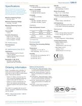
EADS North America Test and Services Note: The EADS North America Test and Services policy is one of continuous develop- ment and improvement. Consequently, the equipment may vary in detail from the descrip- tion and specifications in this publication. Maximum Switching Power Maximum Switching Voltage Maximum Switching Current Insulation Resistance Path Resistance • Open Channel, Input to Ground: • Closed Channel, Input to Ground: Insertion Loss Return Loss/VSWR Peak and Dynamic Current Switching Time (Including Settling) Shock (Functional) Life Expectancy • >100 million mechanical operations...
Open the catalog to page 2All Astronics Test Systems catalogs and technical brochures
 1264c
1264c2 Pages
 4024h
4024h1 Page
 Option 01T
2 Pages
 1256L
1256L2 Pages
 1260-101
2 Pages
 1260-100
2 Pages
 1260-152/172
3 Pages
 1260-120
3 Pages
 1260-150
3 Pages
 1260-136B/C/D
2 Pages
 1260-138A
3 Pages
 1260-134
2 Pages
 1260-167AH/BH
2 Pages
 1260-164AH/BH
2 Pages
 1260-162AH/BH
2 Pages
 1260-145A-G
3 Pages
 1260-116
2 Pages
 1260-117/117A
3 Pages
 1260-118/118A
3 Pages
 3172
31726 Pages
 3152B
3152B6 Pages
 3151B
3151B5 Pages
 3164_2_0
3 Pages
 3156c
3156c5 Pages
 313A
313A1 Page
 6084A-104-DMM
5 Pages
 6084-2105
2 Pages
 PXIe-1803
4 Pages
 PXIe-6943
6 Pages
 VX407C
2 Pages
 VX405C
2 Pages
 203PC-1, 2
3 Pages
 1257A
1257A10 Pages
 1263HPf
2 Pages
 T940
T9408 Pages
 COTS Product Guide December, 2011
339 Pages
 1261B-S-2378
2 Pages
 1261B linear
3 Pages
 1261B
1261B5 Pages
 1260-x153
2 Pages
 1260-x121
2 Pages
 1260-1114
2 Pages
 1260-700
2 Pages
 1260-155
2 Pages
 1260-115
2 Pages
 1260-114
3 Pages
 1260-88
2 Pages
 1260-75
2 Pages
 1260-58
2 Pages
 1260-54
2 Pages
 1260-16
2 Pages
 1260-14
2 Pages
 1260-00C
3 Pages
 1255A
1255A2 Pages


- LIMING management software
- Data logger
- LIMING digital I/O
- LIMING Windows software
- Calibration system
- Temperature datalogger
- LIMING signal amplifier
- Simulation software solution
- Wireless datalogger
- Automated software
- Transceiver module
- LIMING automatic testing device
- Datalogger without display
- Development software
- Multimeter
- Portable calibrator
- Digital multimeter
- Temperature calibration system
- Engineering software
- Test set