Catalog excerpts

User manual
Open the catalog to page 1
Remarks The information provided in the manual on hand have been carefully investigated and processed. Still, we cannot assume any kind of liability regarding completeness or mistakes. However, we are always grateful to get feedback and proposals. Claims for damages are, except in the case of premeditation or negligence, in principle excluded. As a series of versions of this product is available, deviations from the manual on hand might occur, if applicable. We reserve ourselves the right to implement technical modification that serves to optimize of the product without related...
Open the catalog to page 2
ASTECH GmbH
Open the catalog to page 3
ASTECH GmbH
Open the catalog to page 4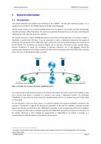
General information General information 1.1 Introduction This manual describes the software and hardware of the VLM500 – DG skin pass measuring system. It is a supplementary manual for the VLM500 speed and length measuring gauge. The DG system consists of up to three VLM500 devices that are wired to one another and that automatically calculate and output differential values. This system was specially developed for use in skin-pass, stretching and rolling stands in the steel and aluminum industries. The system consists of a master VLM500 (DG master) and at least one slave (DG slave 1), as...
Open the catalog to page 5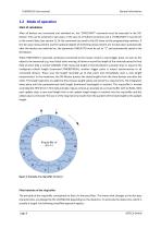
General information 1.2 Mode of operation Start of calculation After all devices are connected and switched on, the "SYNCSTART" command must be executed in the DGMaster. This can be achieved in two ways: in the case of a Profinet connection, bit 2 ("SYNCSTART") must be set in the control byte (see section 2). Or the command can send to the DG slave via the programming interface. If the skin pass measurement and the optional degree of stretching measurement are to take place automatically after the devices are switched on, the parameter SYNCAUTO must be set to “1” and permanently saved in...
Open the catalog to page 6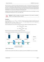
General information The time constant τ is used from the analysis of linear dynamic systems. τ is the time after which the response of a system has reached 63% of a sudden change at the input (step response). Translated to the VLM500-DG system, this means: τ is the length after that 63% of changes in the skin pass characteristics have been processed by the internal processor. Based on this relationship an appropriate setting of the total calculation length (parameter SYNCLENGTH) can be estimated by dividing the desired length by 0.63. Example: If the user wants to see changes in the skin...
Open the catalog to page 7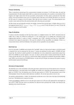
General information Process monitoring There is permanent monitoring of the communication between the devices. If a DG-slave does not send the requested data to the DG-master within 500 ms, an internal communication error counter is incremented. If this happens the length values from the last successful communication are then used to calculate the mass flow values. If 10 communication errors occur in succession with a DG-slave, error E70 (for DG slave 1) or error E71 (for DG slave 2) is output on the DG-master. After that the error counter is reset. The communication error counter is also...
Open the catalog to page 8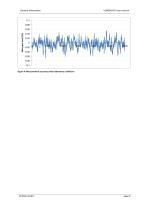
General information Skin pass level [%] Figure 4: Measurement accuracy under laboratory conditions ASTECH GmbH
Open the catalog to page 9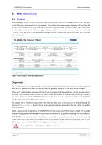
Data transmission Data transmission 2.1 Profinet The VLM500-DG system can be equipped with a Profinet interface. The associated IFPN interface card is installed in the DG master and connects it to the network. This enables the communication between a PLC and the DG master over large distances using standardized network components. The current mass flow measured values can be output synchronously with the trigger. It is also possible to send control commands to the master via Profinet. A small webserver is also available providing a website showing status information about the measuring...
Open the catalog to page 10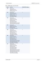
Data transmission Table 1: VLM500 Profinet modes (Profinet IN) SYNCOUTPUT setting 16 Bit Counter 32 Bit Skin pass level 8 Bit VLM – error number 8 Bit Device status 16 Bit Counter 32 Bit Skin pass level 8 Bit VLM - error number 8 Bit Device status 32 Bit velocity of master 32 Bit velocity of slave 1 16 Bit Counter 32 Bit Skin pass level 8 Bit VLM - error number 8 Bit Device status 32 Bit velocity of master 32 Bit velocity of slave 1 16 Bit measurement rate of master 16 Bit measurement rate of slave 1 16 Bit Counter 32 Bit Skin pass level 8 Bit VLM - error number 8 Bit Device status 32 Bit...
Open the catalog to page 11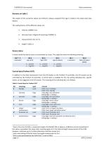
Data transmission Remarks on table 1 The output of the numerical values via Profinet is always unsigned! The sign is coded in the status byte (see below). The scaling factors of the different values are: • skin pass level / degree of stretching: 0,00001 %, Device status In every mode the device status is transmitted as a byte. The single bits have the following meaning: Bit 7 - 5 Status of output ERROR Control byte (Profinet OUT) In addition to the data transmission from the DG-master to the Profinet IO controller, the DG-master can be controlled by the Profinet IO controller. A control...
Open the catalog to page 12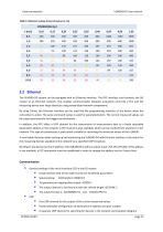
Data transmission Table 3: Minimum output times (all values in ms) 2.2 Ethernet The VLM500-DG system can be equipped with an Ethernet interface. The IFFE interface card connects the DG master to an Ethernet network. This enables communication between evaluation units like a PLC and the measuring device over large distances using standardized network components. By using Telnet, the Ethernet interface can be used like the programming interface of the device when the connection is active. The same command syntax is used for parameterization. The current measured values can be output...
Open the catalog to page 13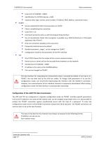
Listen-Port of VLM500 = 33003 identification for ASTECH-devices = 0x05 response data: type, version, serial number, IP-address, MAC-address, connection status Data transmission Service related 8-bit ASCII communication via TCP/IP Client is establishing the connection Listen-Port = 23 Command syntax the same as with the programming interface Use of conventional Telnet client programs is possible (e.g. ASTECH Ethertool or third-party application like HTerm5) Only one connection possible at the same time Password protected access by default Standard password: „wega“, can be changed via TELNET...
Open the catalog to page 14All ASTECH Angewandte Sensortechnik GmbH catalogs and technical brochures
-
LDS10A
2 Pages
-
CROMLAVIEW® CR10
1 Pages
-
LDM41P and LDM42P
2 Pages
-
LDM41E and LDM42E
2 Pages
-
LDM41A and LDM42A
2 Pages
-
CR-TBox
2 Pages
-
CR-COMBox
2 Pages
-
CR500
2 Pages
-
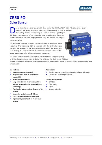
CR50-FO
2 Pages
-
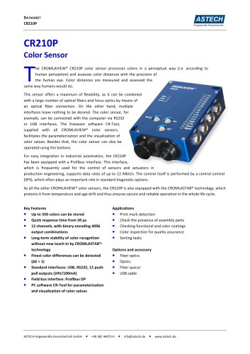
CR210P
2 Pages
-
LDS30A
2 Pages
-
PHSS30x (LDM)
2 Pages
-
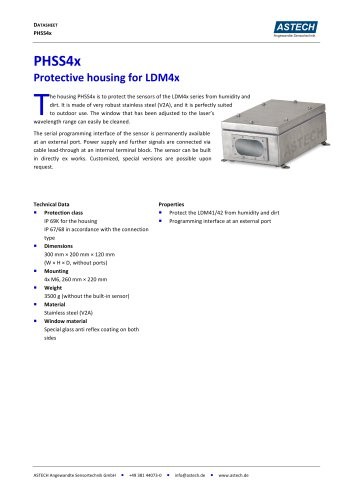
PHSS4x (LDM)
2 Pages
-
PHSS4x-W (LDM)
2 Pages
-
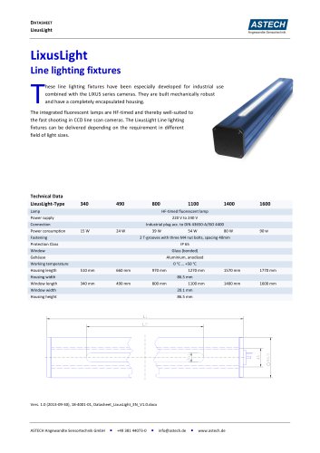
LixusLight
1 Pages
-
CR210E
2 Pages
-
CR200P
2 Pages
-
CR200E
2 Pages
-
CR100-PM
2 Pages
-
CROMLAVIEW® CR100 DataSheet
2 Pages
-
LDM 41/42 P
2 Pages
-
VLM320 Datasheet
2 Pages
-
LDM41 A Datasheet
2 Pages
-
LDM51A LUMOS Datasheet
2 Pages
-
LDS30 Datasheet
2 Pages
-
FOD-M4.0-1100
4 Pages
-
LIXUS-i PN
2 Pages
-
LDM302A
2 Pages
-
CROMLAVIEW® CR50 / CR50FO Manual
12 Pages
-
LDM301A Datasheet
2 Pages
-
CROMLAVIEW® - Product Catalogue
19 Pages


