WS7.5
1 /41Pages

WS7.5
1 /41Pages
Catalog excerpts
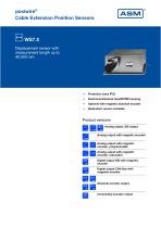
posiwire® Cable Extension Position Sensors WS7.5 Displacement sensor with measurement length up to 40,000 mm Aluminum/stainless steel/EPDM housing Optional with magnetic absolute encoder Redundant version available Product versions Analog output, SSI output Analog output with magnetic encoder Analog output with magnetic encoder, programmable Analog output with magnetic encoder, redundant Digital output SSI with magnetic encoder Digital output CAN Bus with magnetic encoder Absolute encoder output Incremental encoder
Open the catalog to page 1
WS7.5 - Cable Extension Position Sensor Version with analog output, SSI output Specifications Order options Measurement range Analog: quasi infinite Potentiometer 1 kΩ Voltage 0 ... 10 V Current 4 ... 20 mA, 2 wire Current 4 ... 20 mA, 3 wire Current output, programmable Voltage output, programmable Signal conditioner SSI 12 bit Signal conditioner SSI 14 bit Signal conditioner SSI 16 bit Sensing device Precision potentiometer Aluminum, stainless steel and EPDM measuring cable: stainless steel Protection class Cable fixing M4 cable fixing Cable clip Temperature range Order example: WS7.5 – 30000...
Open the catalog to page 2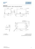
posiwire® WS7.5 Dimensions Measurement range 10000 … 40000 mm, analog output, SSI output Dimensions in mm [inch] Dimensions informative only. For guaranteed dimensions consult factory.
Open the catalog to page 3
WS7.5 - Cable Extension Position Sensor Version with analog output with magnetic encoder Specifications Order options Measurement range Voltage 0.5 ... 10 V Voltage 0.5 ... 4.5 V Current 4 ... 20 mA, 3 wire Signal characteristics Increasing signal (e.g. 4 ... 20 mA) Decreasing signal (e.g. 20 ... 4 mA) Sensing device Magnetic absolute encoder Aluminum, stainless steel and EPDM measuring cable: stainless steel Protection class Cable fixing M4 cable fixing Cable clip Connector M12, 5 pin (standard) Connector M12, 8 pin (DBs_optional) Temperature range Order example: WS7.5 – 30000 – U2 – A – L10...
Open the catalog to page 4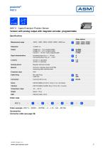
WS7.5 - Cable Extension Position Sensor Version with analog output with magnetic encoder, programmable Specifications Order options Measurement range Voltage 0.5 ... 10 V, programmable Voltage 0.5 ... 4.5 V, programmable Current 4 ... 20 mA, 3 wire, programmable Signal characteristics Increasing signal (e.g. 4 ... 20 mA) Decreasing signal (e.g. 20 ... 4 mA) Sensing device Magnetic absolute encoder Aluminum, stainless steel and EPDM measuring cable: stainless steel Protection class Cable fixing M4 cable fixing Cable clip Temperature range Order example: WS7.5 – 30000 – U2/PMU – A – L10 – M4 –...
Open the catalog to page 5
WS7.5 - Cable Extension Position Sensor Version with analog output with magnetic encoder, redundant Specifications Order options Measurement range Voltage 0.5 ... 10 V, redundant Voltage 0.5 ... 4.5 V, redundant Current 4 ... 20 mA, 3 wire, redundant Signal characteristics Output 1 increasing, output 2 increasing Output 1 increasing, output 2 decreasing Output 1 decreasing, output 2 decreasing Sensing device Magnetic absolute encoder Aluminum, stainless steel and EPDM measuring cable: stainless steel Protection class Cable fixing M4 cable fixing Cable clip Temperature range Order example: WS7.5...
Open the catalog to page 6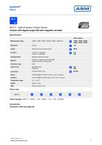
WS7.5 - Cable Extension Position Sensor Version with digital output SSI with magnetic encoder Specifications Order options Measurement range SSI synchronous serial interface Sensing device Magnetic absolute encoder Aluminum, stainless steel and EPDM measuring cable: stainless steel Protection class Cable fixing M4 cable fixing Cable clip Temperature range Order example: WS7.5 – 30000 – 100 – MSSI – L10 – M4 – M12A8 Accessories: Connector cable (see page 39)
Open the catalog to page 7
WS7.5 - Cable Extension Position Sensor Version with digital output CAN Bus with magnetic encoder Specifications Order options Measurement range CANopen CAN SAE J1939 CANopen redundant CAN SAE J1939 redundant Sensing device Magnetic absolute encoder Aluminum, stainless steel and EPDM measuring cable: stainless steel Protection class Cable fixing M4 cable fixing Cable clip Temperature range Order example: WS7.5 – 30000 – MCANOP – L10 – M4 – M12/CAN Accessories: Connector cable (see page 40) Cable forces Measurement range Maximum pull-out force Minimum pull-in force
Open the catalog to page 8
posiwire® WS7.5 Dimensions Measurement range 10000 … 40000 mm, magnetic encoder output Dimensions in mm [inch] Dimensions informative only. For guaranteed dimensions consult factory.
Open the catalog to page 9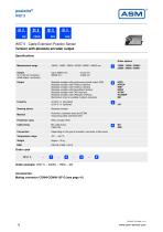
WS7.5 - Cable Extension Position Sensor Version with absolute encoder output Specifications Order options Measurement range Output for 12 bit per revolution (4096 steps / revolution) Absolute encoder with synchronous serial output (SSI) Absolute encoder with Profibus interface Absolute encoder with Interbus interface Absolute encoder with DeviceNet interface Absolute encoder with CAN-interface Absolute encoder with CANopen interface Mechanism only for suitable multiturn encoders HSSI HPROF HINT HDEV HCAN HCANOP ME Sensing device Absolute encoder Aluminum, stainless steel and EPDM measuring cable:...
Open the catalog to page 10
WS7.5 - Cable Extension Position Sensor Version with incremental encoder output Specifications Order options Measurement range Incremental encoder TTL compatible Incremental encoder HTL compatible Sensing device Incremental encoder Aluminum, stainless steel and EPDM measuring cable: stainless steel Protection class Cable fixing M4 cable fixing Cable clip Temperature range Order example: WS7.5 – 30000 – LD5VC – L01 – M4 Accessories: Mating connector CONN-CONIN-12F-G (see page 41) Cable forces Measurement range Maximum pull-out force Minimum pull-in force
Open the catalog to page 11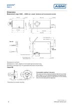
posiwire® WS7.5 Dimensions Measurement range 10000 … 40000 mm; output: absolute and incremental encoder Dimensions in mm [inch] Dimensions D, F and L depend on the encoder type and sensor fixing. Dimensions informative only. For guaranteed dimensions consult factory. Connectable coupling in two parts The outer part of the coupling should be fitted to the encoder shaft. Adjust a 0.5 mm clearance between the fastening and the mounting flanges to give an initial tension on the coupling when the mounting bolts are tightened. Dimensions for encoder mounting
Open the catalog to page 12All ASM Automation Sensorik Messtechnik GmbH catalogs and technical brochures
 System NMG2
4 Pages
 PTK7
PTK79 Pages
 PTK6
PTK69 Pages
 PTK29
PTK297 Pages
 PTDM7
PTDM78 Pages
 PTAM7
PTAM712 Pages
 PTDM6
PTDM68 Pages
 PTAM6
PTAM613 Pages
 PTDM5
PTDM510 Pages
 PTAM5
PTAM513 Pages
 PTAM4
PTAM49 Pages
 PTAM2
PTAM216 Pages
 PTAM27
9 Pages
 PTM29
PTM2910 Pages
 AWS
AWS5 Pages
 PH68
PH6819 Pages
 PH58
PH5821 Pages
 PH36
PH3621 Pages
 PRAS7
PRAS718 Pages
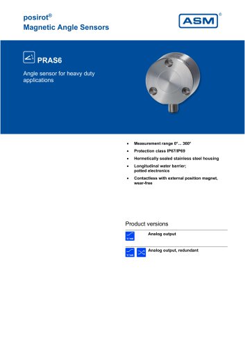 PRAS6
PRAS619 Pages
 PRAS5
PRAS525 Pages
 PRAS4
PRAS48 Pages
 PRAS3
PRAS319 Pages
 PRAS1
PRAS112 Pages
 PRAS29
15 Pages
 PRAS27
16 Pages
 PRAS26
13 Pages
 PRAS20
12 Pages
 PMIB3
PMIB37 Pages
 PMIS3
PMIS38 Pages
 posichron® EasyMount
6 Pages
 PCRP32
18 Pages
 PCST27
26 Pages
 PCST25
27 Pages
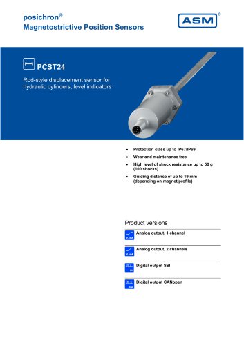 PCST24
29 Pages
 PCRP21
23 Pages
 PCQA24
24 Pages
 PCQA22
24 Pages
 PCFP25
22 Pages
 PCFP24
22 Pages
 PCFP23
24 Pages
 WB100M
21 Pages
 WST 21
9 Pages
 WB21
WB2126 Pages
 WST85
WST856 Pages
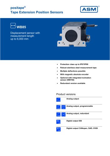 WB85
WB8522 Pages
 WST61
WST616 Pages
 WB61
WB6122 Pages
 WB12
WB1223 Pages
 WB10ZG
20 Pages
 WS7.0
WS7.06 Pages
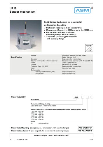 LR19
LR196 Pages
 WS12EX
8 Pages
 WS10EX
8 Pages
 WS58C
WS58C9 Pages
 WS100M
24 Pages
 WS60
WS6012 Pages
 WBT21
WBT2111 Pages
 WS21
WS2125 Pages
 WBT61
WBT617 Pages
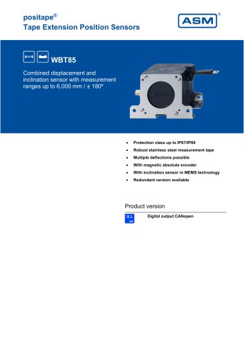 WBT85
WBT857 Pages
 WS85
WS8522 Pages
 WS61
WS6122 Pages
 WS19KT
11 Pages
 WS19KT
16 Pages
 WS17KT
16 Pages
 WS12
WS1239 Pages
 WS10
WS1036 Pages
 WS10ZG
36 Pages
 WS10SG
36 Pages
 WS42C
WS42C8 Pages
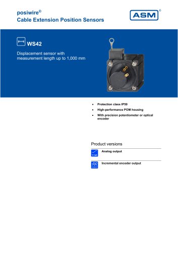 WS42
WS4210 Pages
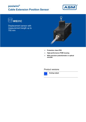 WS31C
WS31C8 Pages
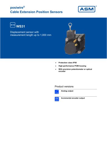 WS31
WS3110 Pages
 PTM27
PTM2710 Pages
 ASM Product Overview
40 Pages


Archived catalogs


- Angular encoder
- Measuring machine
- Incremental rotary encoder
- Digital indicator
- Panel panel meter
- ASM inclinometer
- ASM linear position sensor
- Magnetic rotary encoder
- Linear displacement sensor
- IP67 rotary encoder
- ASM analog position sensor
- ASM digital inclinometer
- DC rotary encoder
- Optical measurement system
- ASM non-contact position sensor
- ASM 2-axis inclinometer
- Stainless steel rotary encoder