PTK7
1 /9Pages

PTK7
1 /9Pages
Catalog excerpts

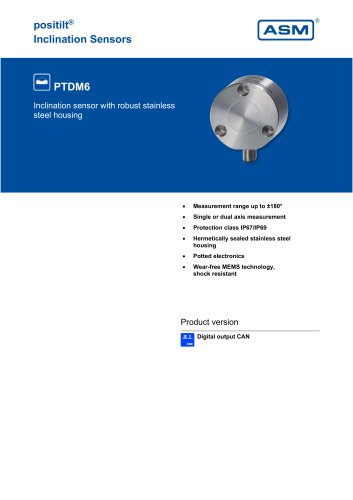
positilt® Gyro-compensated Inclination Sensors PTK7 Dynamic inclination sensor with robust stainless steel housing, also for hygienic applications Measurement range ±180°, 2 axes Hermetically sealed stainless steel housing Potted electronics Wear-free MEMS technology User selectable axis orientation (optional) Product versions Digita
Open the catalog to page 1
PTK7 - Dynamic inclination sensor Version with digital output CAN Specifications Order options Output Measurement range Linearity (static) Housing material Stainless steel EN 1.4404 (AISI 316L) Protection class IP67/IP69 (connector output with IP67/IP69 connector) Connector M12 axial, 5 pin Connector M12 radial, 5 pin Temperature range Order example: PTK7 – CANOP – M12R5/CAN Accessories: Connector cable (see page 9)
Open the catalog to page 2
Dimensions Connector M12, axial Dimensions in mm [inch]. Dimensions informative only. For guaranteed dimensions consult factory.
Open the catalog to page 3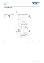
Dimensions in mm [inch]. Dimensions informative only. For guaranteed dimensions consult factory.
Open the catalog to page 4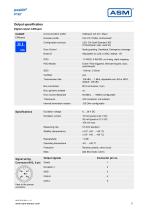
Output specification Digital output CANopen CANOP Communication profile Encoder profile Configuration services LSS, CiA Draft Standard 305 (Transmission rate, node ID) Error Control Node guarding, Heartbeat, Emergency message 1 TxPDO, 0 RxPDO, no linking, static mapping Event-/Time triggered, Remote-request, Sync cyclic/acyclic Transmission rate 125 kBit … 1 Mbit, adjustable via LSS or SDO, default: 125 kBit Error Control Baudrate 50 kBit/s … 1 MBit/s configurable Internal termination resistor Excitation voltage Excitation current Measuring rate Stability (temperature) Operating temperature Reverse...
Open the catalog to page 5
ISO 11898, Basic and Full CAN 2.0 B extended message format with 29-bit identifier Communication profile Transmission rate Internal termination resistor NAME - Unique device identifier Name Fields Field value Byte order Byte value Arbitrary Address Capable Industry Group Function Instance Vehicle System instance Vehicle System Reserved Function Manufacturer Code Identity Number Proprietary PGN Manufacturer specific Parameter Group Numbers Configuration data Process data Proprietary-B (PDU2 broadcast); nn Group Extension (PS) configurable
Open the catalog to page 6
Excitation current Measuring rate Stability (temperature) Operating temperature Reverse polarity, short circuit Signal wiring Connector M12, 5 pin Excitation voltage Output signals CAN-H View to the sensor connector
Open the catalog to page 7
PTK7 – Output characteristic and axis orientation For CAN output, the axis orientation can be set by the user via software. Sensor position as shown equals 0°. 2 measuring axes Axis orientation 2A Output signal
Open the catalog to page 8
Accessories Connector/bus cable M12, 5 pin CAN-Bus The 5-lead shielded cable is supplied with a female 5 pin M12 connector at one end and a male 5 pin M12 connector at the other end. Available lengths are 0.3 m, 2 m, 5 and 10 m. Cable diameter: 6.7 ±0.2 mm Order code T-connector for bus cable M12, 5 pin CAN-Bus Order code Terminating resistor M12, 5 pin CAN-Bus Order code Applicable for cable carriers Maximum movement speed Maximum acceleration Minimum bending radius
Open the catalog to page 9All ASM Automation Sensorik Messtechnik GmbH catalogs and technical brochures
 System NMG2
4 Pages
 PTK6
PTK69 Pages
 PTK29
PTK297 Pages
 PTDM7
PTDM78 Pages
 PTAM7
PTAM712 Pages
 PTDM6
PTDM68 Pages
 PTAM6
PTAM613 Pages
 PTDM5
PTDM510 Pages
 PTAM5
PTAM513 Pages
 PTAM4
PTAM49 Pages
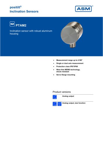 PTAM2
PTAM216 Pages
 PTAM27
9 Pages
 PTM29
PTM2910 Pages
 AWS
AWS5 Pages
 PH68
PH6819 Pages
 PH58
PH5821 Pages
 PH36
PH3621 Pages
 PRAS7
PRAS718 Pages
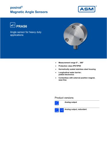 PRAS6
PRAS619 Pages
 PRAS5
PRAS525 Pages
 PRAS4
PRAS48 Pages
 PRAS3
PRAS319 Pages
 PRAS1
PRAS112 Pages
 PRAS29
15 Pages
 PRAS27
16 Pages
 PRAS26
13 Pages
 PRAS20
12 Pages
 PMIB3
PMIB37 Pages
 PMIS3
PMIS38 Pages
 posichron® EasyMount
6 Pages
 PCRP32
18 Pages
 PCST27
26 Pages
 PCST25
27 Pages
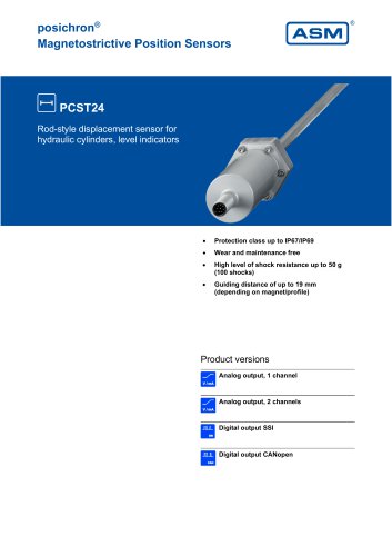 PCST24
29 Pages
 PCRP21
23 Pages
 PCQA24
24 Pages
 PCQA22
24 Pages
 PCFP25
22 Pages
 PCFP24
22 Pages
 PCFP23
24 Pages
 WB100M
21 Pages
 WST 21
9 Pages
 WB21
WB2126 Pages
 WST85
WST856 Pages
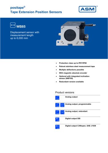 WB85
WB8522 Pages
 WST61
WST616 Pages
 WB61
WB6122 Pages
 WB12
WB1223 Pages
 WB10ZG
20 Pages
 WS7.0
WS7.06 Pages
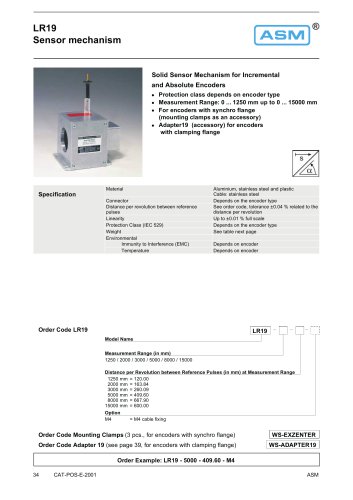 LR19
LR196 Pages
 WS12EX
8 Pages
 WS10EX
8 Pages
 WS58C
WS58C9 Pages
 WS100M
24 Pages
 WS60
WS6012 Pages
 WS7.5
WS7.541 Pages
 WBT21
WBT2111 Pages
 WS21
WS2125 Pages
 WBT61
WBT617 Pages
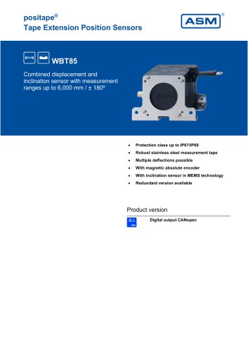 WBT85
WBT857 Pages
 WS85
WS8522 Pages
 WS61
WS6122 Pages
 WS19KT
11 Pages
 WS19KT
16 Pages
 WS17KT
16 Pages
 WS12
WS1239 Pages
 WS10
WS1036 Pages
 WS10ZG
36 Pages
 WS10SG
36 Pages
 WS42C
WS42C8 Pages
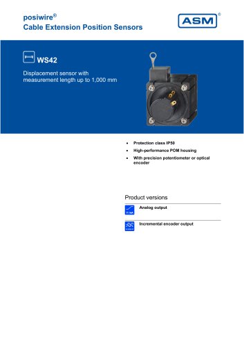 WS42
WS4210 Pages
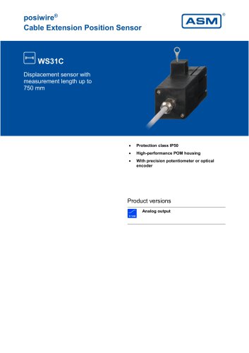 WS31C
WS31C8 Pages
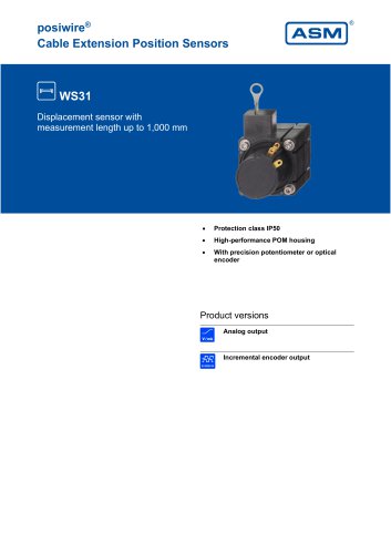 WS31
WS3110 Pages
 PTM27
PTM2710 Pages
 ASM Product Overview
40 Pages


Archived catalogs


- Angular encoder
- Measuring machine
- ASM incremental encoder
- Incremental rotary encoder
- Digital indicator
- Panel panel meter
- ASM position sensor
- ASM inclinometer
- ASM linear position sensor
- Magnetic rotary encoder
- Displacement transducer
- Linear displacement sensor
- IP67 rotary encoder
- ASM analog position sensor
- ASM digital inclinometer
- DC rotary encoder
- Optical measurement system
- ASM non-contact position sensor
- ASM 2-axis inclinometer
- Stainless steel rotary encoder