PRDS2_2017
1 /21Pages
PRDS2_2017
1 /21Pages
Catalog excerpts

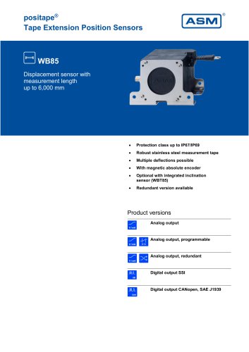
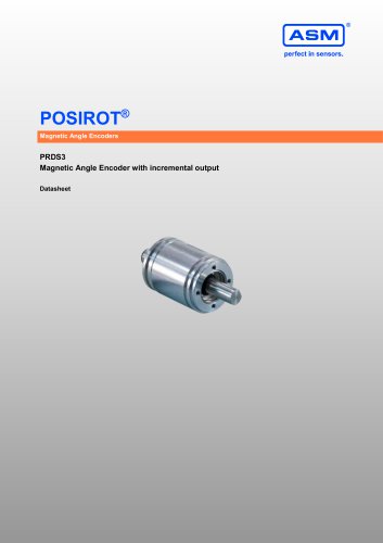
Magnetic Angle Encoders PRDS2 Magnetic Angle Encoder with incremental output Datasheet
Open the catalog to page 1
Copyright ASM Automation Sensorik Messtechnik GmbH Am Bleichbach 18-24 85452 Moosinning Germany The information presented in this data sheet does not form part of any quotation or contract, is believed to be accurate and reliable and may be changed without notice. No liability will be accepted by ASM for any consequence of its use. Publication thereof does not convey nor imply any license under patent or industrial or intellectual property rights. Applications that are described herein for any of these products are for illustrative purpose only. ASM makes no representation or warranty that...
Open the catalog to page 2
Incremental output Sensor features • Incremental output Magnetic measurement principle Non-contact with external position magnet, no wear Housing: Aluminium Specifications Output Incremental encoder output RS422-/HTL compatible, filtered output Measurement range Resolution (pulses per revolution) Rated distance sensor / magnet Depending on the position magnet Protection class IP67/IP69 (connector output with IP67/IP69 connector cable) IP67 (cable output) Clamps, mounting plate 5-pin connector M12 Cable, standard length 2 m Temperature range 50 g approx. (without cable)
Open the catalog to page 4
1 Resolution (pulses per revolution) 256 / 1024 = RS422 compatible output with excitation 5 V DC, filtered output = RS422 compatible output with excitation 10 ... 36 V, filtered output = HTL compatible output with excitation 18 ... 36 V, filtered output = 8-pin connector M12, axial = 8-pin connector M12, radial = Cable, standard length 2 m Accessories: Connector cable (see page 20) Position magnets (see from page 9) Mounting (see page 14)
Open the catalog to page 5
Dimensions Connector M12, axial A – Position magnet B – Measuring area C – Marking D – Connector M12 E – Mounting clamps PRPT-BFS1 Dimensions in mm [inch]. Weight approx. 50 g. Dimensions informative only. For guaranteed dimensions consult factory.
Open the catalog to page 6
A – Position magnet B – Measuring area C – Marking D – Connector M12 Dimensions in mm [inch]. Weight approx. 50 g. Dimensions informative only. For guaranteed dimensions consult factory.
Open the catalog to page 7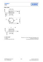
Cable output A – Position magnet B – Measuring area C – Marking D – Mounting clamps PRPT-BFS1 Dimensions in mm [inch]. Weight without cable approx. 40 g. Dimensions informative only. For guaranteed dimensions consult factory.
Open the catalog to page 8
zinc coated steel, plastic A misalignment of the position magnet has an effect on the linearity. Dimensions in mm [inch]. Dimensions informative only. For guaranteed dimensions please consult factory.
Open the catalog to page 9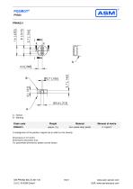
zinc coated steel; plastic A misalignment of the position magnet has an effect on the linearity. Dimensions in mm [inch] Dimensions informative only. For guaranteed dimensions please consult factory.
Open the catalog to page 10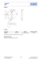
zinc coated steel, plastic A misalignment of the position magnet has an effect on the linearity. Dimensions in mm [inch]. Dimensions informative only For guaranteed dimensions please consult factory.
Open the catalog to page 11
A – Sensor B – Marking C – Notch A misalignment of the position magnet has an effect on the linearity. Dimensions in mm [inch]. Dimensions informative only. For guaranteed dimensions please consult factory.
Open the catalog to page 12
A – Sensor B – Marking C – Thread M10 A misalignment of the position magnet has an effect on the linearity. Dimensions in mm [inch]. Dimensions informative only. For guaranteed dimensions please consult factory.
Open the catalog to page 13
Mounting plates Mounting possibilities PRAS2/PRDS2 and PRAS3/PRDS3 PRPT-BPL1 + PRPT-BFS1 (Mounting plates for screw mounting + mounting clamp) PRPT-BPL2 + PRPT-BFS1 (Mounting plates for welding assembly + mounting clamp) PRPT-BPL1 + PRPT-BFS2 (Mounting plates for screw mounting + mounting bracket) PRPT-BPL2 + PRPT-BFS2 (Mounting plates for welding assembly + mounting bracket)
Open the catalog to page 14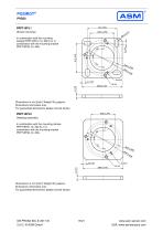
PRPT-BPL1 (Screw mounting) In combination with the mounting clamps PRPT-BFS1 (3 x M2.5) or in combination with the mounting bracket PRPT-BFS2 (3 x M4). Dimensions in mm [inch]. Weight 30 g approx. Dimensions informative only. For guaranteed dimensions please consult factory. PRPT-BPL2 (Welding assembly) In combination with the mounting clamps PRPT-BFS1 (3 x M2.5) or in combination with the mounting bracket PRPT-BFS2 (3 x M4). Dimensions in mm [inch]. Weight 30 g approx. Dimensions informative only. For guaranteed dimensions please consult factory.
Open the catalog to page 15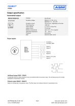
Output specification Incremental output RS5V(F)/RS24V(F) Excitation voltage RS5V(F): 5 V DC ±10 % RS24V(F): 10 ... 36 V DC 100 mA max., depending on the load <500 kHz ̅ ̅ ̅ A, A, B, B, Z, Z Push-Pull 10 mA max. ±50 x 10-6 / °C f.s. (typical) -40 ... +85 °C Short circuit DIN EN 61326-1:2013 Excitation current Pulse frequency Output signals Output current Stability (temperature) Operating temperature Protection EMC Output signals Excitation + Excitation GND Signal A Signal A Signal B Signal B Signal Z (ref. puls) Signal Z Unfiltered output RS5V / RS24V A preferred maximum pulse frequency has to...
Open the catalog to page 16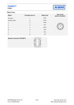
POSIROT® PRDS2 Signal wiring Signal Cable color View to the sensor connector
Open the catalog to page 17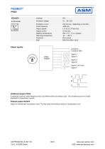
Excitation voltage Excitation current Pulse frequency Output signals Output current Stability (temperature) Operating temperature Protection EMC 100 mA max., depending on the load <500 kHz ̅ ̅ ̅ A, A, B, B, Z, Z Push-Pull 10 mA max. ±50 x 10-6 / °C f.s. (typical) -40 ... +85 °C Short circuit DIN EN 61326-1:2013 Output signals Excitation+ Excitation GND Signal A Signal A Signal B Signal B Signal Z (ref. puls) Signal Z Unfiltered output HT24V A preferred maximum pulse frequency has to be defined within the product code. This will take account for limited bandwidth of downstream counter. Filtered...
Open the catalog to page 18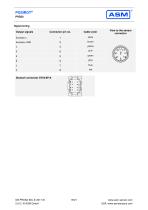
Signal wiring Output signals Cable color View to the sensor connector
Open the catalog to page 19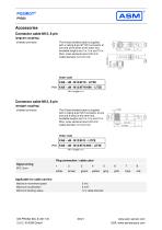
Accessories Connector cable M12, 8 pin (angular coupling) shielded connector The 8-lead shielded cable is supplied with a mating 8-pin 90° M12 connector at one end and 8 wires at the other end. Available lengths are 2 m, 5 m and 10 m. Wire: cross sectional area 0.25 mm² Cable diameter: 6.3 ±0.2 mm Order code KAB - xM - M12/8F/W - LITZE IP69: KAB - xM - M12/8F/W/69K - LITZE xM = length in m Connector cable M12, 8 pin (straight coupling) The 8-lead shielded cable is supplied with a mating 8-pin M12 connector at one end and 8 wires at the other end. Available lengths are 2 m, 5 m and 10 m. Wire:...
Open the catalog to page 20All ASM Automation Sensorik Messtechnik GmbH catalogs and technical brochures
 System NMG2
4 Pages
 PTK7
PTK79 Pages
 PTK6
PTK69 Pages
 PTK29
PTK297 Pages
 PTDM7
PTDM78 Pages
 PTAM7
PTAM712 Pages
 PTDM6
PTDM68 Pages
 PTAM6
PTAM613 Pages
 PTDM5
PTDM510 Pages
 PTAM5
PTAM513 Pages
 PTAM4
PTAM49 Pages
 PTAM2
PTAM216 Pages
 PTAM27
9 Pages
 PTM29
PTM2910 Pages
 AWS
AWS5 Pages
 PH68
PH6819 Pages
 PH58
PH5821 Pages
 PH36
PH3621 Pages
 PRAS7
PRAS718 Pages
 PRAS6
PRAS619 Pages
 PRAS5
PRAS525 Pages
 PRAS4
PRAS48 Pages
 PRAS3
PRAS319 Pages
 PRAS1
PRAS112 Pages
 PRAS29
15 Pages
 PRAS27
16 Pages
 PRAS26
13 Pages
 PRAS20
12 Pages
 PMIB3
PMIB37 Pages
 PMIS3
PMIS38 Pages
 posichron® EasyMount
6 Pages
 PCRP32
18 Pages
 PCST27
26 Pages
 PCST25
27 Pages
 PCST24
29 Pages
 PCRP21
23 Pages
 PCQA24
24 Pages
 PCQA22
24 Pages
 PCFP25
22 Pages
 PCFP24
22 Pages
 PCFP23
24 Pages
 WB100M
21 Pages
 WST 21
9 Pages
 WB21
WB2126 Pages
 WST85
WST856 Pages
 WB85
WB8522 Pages
 WST61
WST616 Pages
 WB61
WB6122 Pages
 WB12
WB1223 Pages
 WB10ZG
20 Pages
 WS7.0
WS7.06 Pages
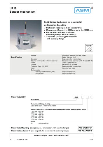 LR19
LR196 Pages
 WS12EX
8 Pages
 WS10EX
8 Pages
 WS58C
WS58C9 Pages
 WS100M
24 Pages
 WS60
WS6012 Pages
 WS7.5
WS7.541 Pages
 WBT21
WBT2111 Pages
 WS21
WS2125 Pages
 WBT61
WBT617 Pages
 WBT85
WBT857 Pages
 WS85
WS8522 Pages
 WS61
WS6122 Pages
 WS19KT
11 Pages
 WS19KT
16 Pages
 WS17KT
16 Pages
 WS12
WS1239 Pages
 WS10
WS1036 Pages
 WS10ZG
36 Pages
 WS10SG
36 Pages
 WS42C
WS42C8 Pages
 WS42
WS4210 Pages
 WS31C
WS31C8 Pages
 WS31
WS3110 Pages
 PTM27
PTM2710 Pages
 ASM Product Overview
40 Pages


Archived catalogs


- Angular encoder
- Measuring machine
- Incremental rotary encoder
- Digital indicator
- Panel panel meter
- ASM position sensor
- ASM inclinometer
- ASM linear position sensor
- Magnetic rotary encoder
- Displacement transducer
- Linear displacement sensor
- IP67 rotary encoder
- ASM analog position sensor
- ASM digital inclinometer
- DC rotary encoder
- Optical measurement system
- ASM non-contact position sensor
- ASM 2-axis inclinometer
- Stainless steel rotary encoder