PCST25
1 /27Pages

PCST25
1 /27Pages
Catalog excerpts

posichron® Magnetostrictive Position Sensors PCST25 Rod-style displacement sensor for hydraulic cylinders, level indicators Wear and maintenance free High level of shock resistance up to 50 g (100 shocks) Guiding distance of up to 19 mm (depending on magnet/profile) Product versions Analog output, 1 channel Analog output, 2 channels
Open the catalog to page 1
PCST25 - Rod-style Magnetostricitve Position Sensor Version with analog output, 1 channel Specification Order options, 1 channel Mounting Thread M18 x 1,5 Thread ¾"-16UNF Plug-in version Working pressure 400 bar, other values on request Measurement range 100 ... 5750 (in 10 mm increments) other lengths upon request 0 ... 10 V signal conditioner U1 with alarm_HOLD 0.5 ... 10 V signal conditioner U2 with alarm_LOW; U2 with alarm_HOLD 0.5 ... 4.5 V signal conditioner U8 with alarm_LOW; U8 with alarm_HOLD 4 ... 20 mA signal conditioner (3 wire) I1 with alarm_LOW; I1with alarm_HOLD Position magnet...
Open the catalog to page 2
PCST25 - Rod-style Magnetostricitve Position Sensor Version with analog output, 2 channels Specifications Order options, 2 channels Mounting Thread M18 x 1,5 Thread ¾"-16UNF Plug-in version Working pressure 400 bar, other values on request Measurement range 100 ... 5750 (in 10 mm increments) other lengths upon request 0 ... 10 V signal conditioner U1 with alarm_HOLD 0.5 ... 10 V signal conditioner U2 with alarm_LOW; U2 with alarm_HOLD 0.5 ... 4.5 V signal conditioner U8 with alarm_LOW; U8 with alarm_HOLD 4 ... 20 mA signal conditioner (3 wire) I1 with alarm_LOW; I1with alarm_HOLD Function and...
Open the catalog to page 3
1) VZx.x = velocity with direction detection (with 1 magnet only), in steps of 0.1 m/s Example: VZ1.5 towards start position 2) VAx.x = velocity without direction detection (with 1 magnet only), in steps of 0.1 m/s Example: VA1.5 towards start position Accessories: Position magnets (see from page 13)
Open the catalog to page 4
PCST25 - Rod-style Magnetostricitve Position Sensor Version with digital output SSI Specifications Order options Mounting Thread M18 x 1,5 Thread ¾"-16UNF Plug-in version Working pressure 400 bar, other values on request Measurement range 100 ... 5750 (in 10 mm increments) other lengths upon request Synchronous serial interface (SSI) Output code Gray Dual Number of data bits Sampling rate Up to 1 kHz, depending on the measurement range Housing material Sensor rod: stainless steel EN 1.4404 (AISI 316L), head: AlMgSi Protection class IP67 (optional IP67/IP69; connector version: with mating connector...
Open the catalog to page 5
PCST25 - Rod-style Magnetostricitve Position Sensor Version with digital output CANopen Specifications Order options Mounting Thread M18 x 1,5 Thread ¾"-16UNF Plug-in version Working pressure 400 bar, other values on request Measurement range 100 ... 5750 (in 10 mm increments) other lengths upon request CANopen-Bus CANopen-Bus with integrated terminating resistance CAN SAE J1939 CAN SAE J1939-Bus with integrated terminating resistance Sampling rate Up to 1 kHz, depending on the measurement range Housing material Sensor rod: stainless steel EN 1.4404 (AISI 316L), head: AlMgSi Protection class...
Open the catalog to page 6
Dimensions Cable output, M18 flange C D = M 18x1,5 A PCSTM AG A – Start position B – End position C – Total length = Measurement length + 97 [3.819] (e.g. 197 [7.756]) D – Flange M18 x 1.5 E – Measurement length (e.g. 100 [3.937]) Cable: outer diameter 5.2 mm ±0.2 mm Wire cross sectional area 0.14 mm2 Dimensions in mm [inch] Dimensions informative only. For guaranteed dimensions consult factory. Cable output, with flange 3/4” C D = 3/4-16 UNF - 2A 15,75 [.620] A – Start position B – End position C – Total length = Measurement length + 97 [3.819] (e.g. 197 [7.756]) D – Flange 3/4”-16UNF-2A E –...
Open the catalog to page 7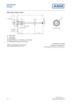
Cable output, Plug-in version C D = M 18x1,5 15,75 [0.620] A – Start position B – End position C – Total length = Measurement length + 99 [3.898] (e.g. 199 [7.835]) D – Measurement length (e.g. 100 [3.937]) Cable: outer diameter 5.2 mm ±0.2 mm Wire cross sectional area 0.14 mm2 Dimensions in mm [inch] Dimensions informative only. For guaranteed dimensions consult factory.
Open the catalog to page 8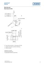
Mounting sets Mounting hole M18 B – Drive hole and pivot M18 x 1.5 according to ISO 6149 C – Diameter of the plane area without marking ring D – Effective diameter Dimensions in mm [inch] Dimensions informative only. For guaranteed dimensions consult factory.
Open the catalog to page 9
B – Drive hole according to ISO 11926-1 UN/UNF thread 2B according to ANSI B1.1/ISO 725 Pivot according to ISO 11926-2 and 3 UN/UNF thread 2A according to ANSI B1.1/ISO 725 Sealing by O-ring C – Effective diameter Dimensions in mm [inch] Dimensions informative only. For guaranteed dimensions consult factory.
Open the catalog to page 10
O-ring sealing O-ring sealing (M18) for: PCST24-M18... PCST25-M18... PCST27-M18... Dimensions in mm [inch] Dimensions informative only. For guaranteed dimensions consult factory. Order code PCST – OR – M18 Dimensions in mm [inch] Dimensions informative only. For guaranteed dimensions consult factory. Order code PCST – OR – Z3/4
Open the catalog to page 11
O-ring sealing (Plug-in version) for: PCST25-SV A – Supporting ring B – O-Ring A – Threaded pin B – Supporting ring C – O-Ring Dimensions in mm [inch] Dimensions informative only. For guaranteed dimensions consult factory. Order code PCST – OR – SV
Open the catalog to page 12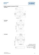
Position magnets for posichron®-PCST PCSTMAG1 Dimensions in mm [inch] Dimensions informative only. For guaranteed dimensions consult factory. Other designs can be realized on request.
Open the catalog to page 13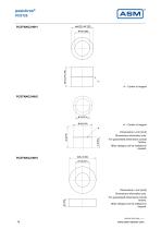
A – Center of magnet Dimensions in mm [inch] Dimensions informative only. For guaranteed dimensions consult factory. Other designs can be realized on request. Dimensions in mm [inch] Dimensions informative only. For guaranteed dimensions consult factory. Other designs can be realized on request.
Open the catalog to page 14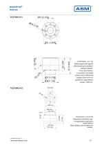
PCSTMAG2 - G1 / G2 Sliding magnet with special self-lubricating and abrasion -resistant material. To be used if sensor is mounted in horizontal position and a mechanical support of the rod is not possible for measurement ranges >1000 mm. Dimensions in mm [inch] Dimensions informative only. For guaranteed dimensions consult factory. Other designs can be realized on request.
Open the catalog to page 15All ASM Automation Sensorik Messtechnik GmbH catalogs and technical brochures
 System NMG2
4 Pages
 PTK7
PTK79 Pages
 PTK6
PTK69 Pages
 PTK29
PTK297 Pages
 PTDM7
PTDM78 Pages
 PTAM7
PTAM712 Pages
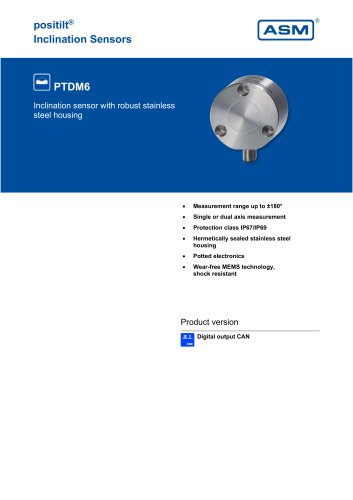 PTDM6
PTDM68 Pages
 PTAM6
PTAM613 Pages
 PTDM5
PTDM510 Pages
 PTAM5
PTAM513 Pages
 PTAM4
PTAM49 Pages
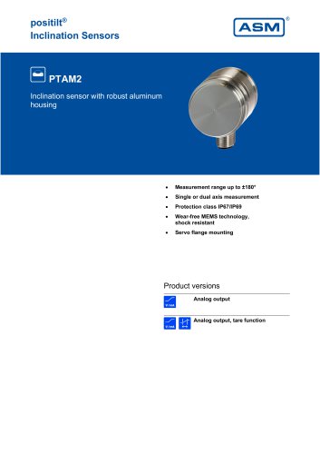 PTAM2
PTAM216 Pages
 PTAM27
9 Pages
 PTM29
PTM2910 Pages
 AWS
AWS5 Pages
 PH68
PH6819 Pages
 PH58
PH5821 Pages
 PH36
PH3621 Pages
 PRAS7
PRAS718 Pages
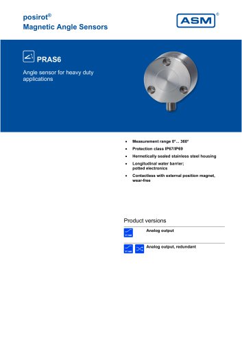 PRAS6
PRAS619 Pages
 PRAS5
PRAS525 Pages
 PRAS4
PRAS48 Pages
 PRAS3
PRAS319 Pages
 PRAS1
PRAS112 Pages
 PRAS29
15 Pages
 PRAS27
16 Pages
 PRAS26
13 Pages
 PRAS20
12 Pages
 PMIB3
PMIB37 Pages
 PMIS3
PMIS38 Pages
 posichron® EasyMount
6 Pages
 PCRP32
18 Pages
 PCST27
26 Pages
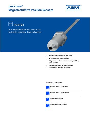 PCST24
29 Pages
 PCRP21
23 Pages
 PCQA24
24 Pages
 PCQA22
24 Pages
 PCFP25
22 Pages
 PCFP24
22 Pages
 PCFP23
24 Pages
 WB100M
21 Pages
 WST 21
9 Pages
 WB21
WB2126 Pages
 WST85
WST856 Pages
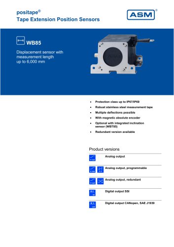 WB85
WB8522 Pages
 WST61
WST616 Pages
 WB61
WB6122 Pages
 WB12
WB1223 Pages
 WB10ZG
20 Pages
 WS7.0
WS7.06 Pages
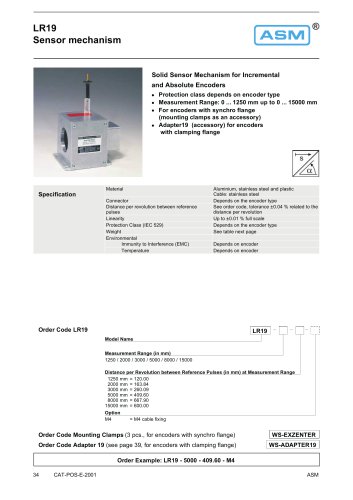 LR19
LR196 Pages
 WS12EX
8 Pages
 WS10EX
8 Pages
 WS58C
WS58C9 Pages
 WS100M
24 Pages
 WS60
WS6012 Pages
 WS7.5
WS7.541 Pages
 WBT21
WBT2111 Pages
 WS21
WS2125 Pages
 WBT61
WBT617 Pages
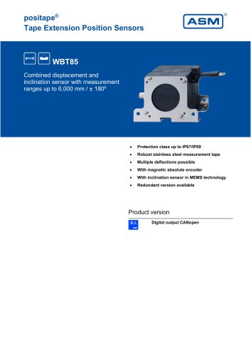 WBT85
WBT857 Pages
 WS85
WS8522 Pages
 WS61
WS6122 Pages
 WS19KT
11 Pages
 WS19KT
16 Pages
 WS17KT
16 Pages
 WS12
WS1239 Pages
 WS10
WS1036 Pages
 WS10ZG
36 Pages
 WS10SG
36 Pages
 WS42C
WS42C8 Pages
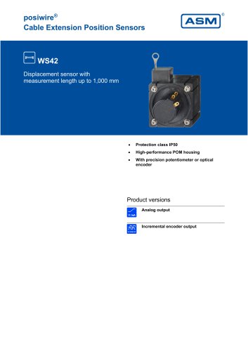 WS42
WS4210 Pages
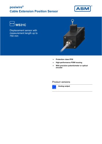 WS31C
WS31C8 Pages
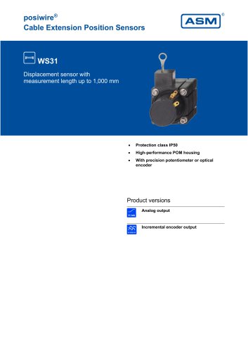 WS31
WS3110 Pages
 PTM27
PTM2710 Pages
 ASM Product Overview
40 Pages


Archived catalogs


- Angular encoder
- Measuring machine
- ASM incremental encoder
- Incremental rotary encoder
- Digital indicator
- Panel panel meter
- ASM inclinometer
- ASM linear position sensor
- Magnetic rotary encoder
- Linear displacement sensor
- IP67 rotary encoder
- ASM analog position sensor
- ASM digital inclinometer
- DC rotary encoder
- Optical measurement system
- ASM non-contact position sensor
- ASM 2-axis inclinometer
- Stainless steel rotary encoder