

PCRP21

PCRP21
- Protection Class: IP64
- Shock Resistance: Up to 50 g (100 shocks)
- Measurement Range: 100 to 5750 mm in 10 mm increments
- Temperature Range: -40 to +85°C
- Housing Material: AIMgSi1 / Zn / V4A
- Analog: Offers 1 and 2 channel outputs with various voltage and current options, including alarm functionalities.
- Digital: Includes SSI and CANopen outputs, supporting high-resolution data transmission and integrated terminating resistance options.
- Resolution: 16 bit full scale, minimum 10 µm
- Sampling Rate: Up to 1 kHz
- Linearity: ±0.10% for ranges >500 mm, ±0.5 mm for ranges ≤500 mm
- Repeatability: ±3 µm
- Mounting Set: PCRP21-BFS4
- Connection: M12 connector, 8 pin, with standard cable length of 2 m
Catalog excerpts

posichron® Magnetostrictive Position Sensors PCRP21 Displacement sensor in round profile for standard industrial applications Also available with guided position magnet Wear and maintenance free High level of shock resistance up to 50 g (100 shocks) Guiding distance of up to 19 mm (depending on magnet/profile) Product versions Analog output, 1 channel Analog output, 2 channels Digital output
Open the catalog to page 1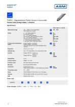
PCRP21 - Magnetostricitve Position Sensor in round profile Version with analog output, 1 channel Specifications Order options, 1 channel Measurement range 100 ... 5750 (in 10 mm increments) other lengths upon request 0 ... 10 V signal conditioner U1 with alarm_HOLD 0.5 ... 10 V signal conditioner U2 with alarm_LOW; U2 with alarm_HOLD 0.5 ... 4.5 V signal conditioner U8 with alarm_LOW; U8 with alarm_HOLD 4 ... 20 mA signal conditioner (3 wire) I1 with alarm_LOW; I1with alarm_HOLD Function and characteristics output Position magnet 1, increasing Position magnet 1, decreasing Start value, direction...
Open the catalog to page 2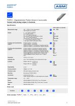
PCRP21 - Magnetostricitve Position Sensor in round profile Version with analog output, 2 channels Specifications Order options, 2 channels Measurement range 100 ... 5750 (in 10 mm increments) other lengths upon request 0 ... 10 V signal conditioner U1 with alarm_HOLD 0.5 ... 10 V signal conditioner U2 with alarm_LOW; U2 with alarm_HOLD 0.5 ... 4.5 V signal conditioner U8 with alarm_LOW; U8 with alarm_HOLD 4 ... 20 mA signal conditioner (3 wire) I1 with alarm_LOW; I1with alarm_HOLD Function and characteristics, output 1 Position magnet 1, increasing Position Magnet 1, decreasing Difference magnet...
Open the catalog to page 3
1) VZx.x = velocity with direction detection (with 1 magnet only), in steps of 0.1 m/s Example: VZ1.5 towards start position 2) VAx.x = velocity without direction detection (with 1 magnet only), in steps of 0.1 m/s Example: VA1.5 towards start position Accessories: Connector cable (see page 22) Position magnets (see page 11) Mounting set (see page 10)
Open the catalog to page 4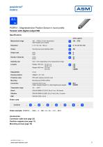
PCRP21 - Magnetostricitve Position Sensor in round profile Version with digital output SSI Specifications Order options Measurement range 100 ... 5750 (in 10 mm increments) other lengths upon request Synchronous serial interface (SSI) Output code Gray Dual Number of data bits Sampling rate Up to 1 kHz, depending on the measurement range Housing material Protection class IP64 (with mating connector only) Connector M12, 8 pin Cable, standard length 2 m; other lengths upon request Temperature range Order example: PCRP21 – 1000 – 5 – SSI / G / 24 ‒ L10 – M12 Accessories: Connector cable (see page...
Open the catalog to page 5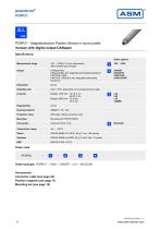
PCRP21 - Magnetostricitve Position Sensor in round profile Version with digital output CANopen Specifications Order options Measurement range 100 ... 5750 (in 10 mm increments) other lengths upon request CANopen-Bus CANopen-Bus with integrated terminating resistance CAN SAE J1939 CAN SAE J1939-Bus with integrated terminating resistance Sampling rate Up to 1 kHz, depending on the measurement range Housing material Protection class IP64 (with mating connector only) Temperature range Order example: PCRP21 – 1000 – CANOP – L10 – M12/CAN Accessories: Connector cable (see page 23) Position magnets...
Open the catalog to page 6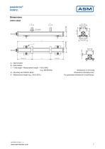
Dimensions Cable output B PCM A G5 A – Start position B – End position C – Total length = Measurement length + 150 [5.906] (e.g. 250 [9.843]) D – Mounting set PCRP21-BFS4 E – Measurement length (e.g. 100 [3.937] ) Dimensions in mm [inch] Dimensions informative only. For guaranteed dimensions consult factory.
Open the catalog to page 7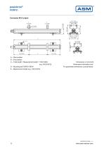
A – Start position B – End position C – Total length = Measurement length + 152 [5.984] (e.g. 252 [9.921]) D – Mounting set PCRP21-BFS4 E – Measurement length (e.g. 100 [3.937]) Dimensions in mm [inch] Dimensions informative only. For guaranteed dimensions consult factory.
Open the catalog to page 8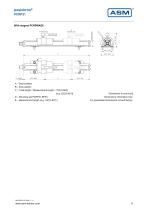
A – Start position B – End position C – Total length = Measurement length + 152 [5.984] (e.g. 252 [9.921]) D – Mounting set PCRP21-BFS4 E – Measurement length (e.g. 100 [3.937] ) Dimensions in mm [inch] Dimensions informative only. For guaranteed dimensions consult factory.
Open the catalog to page 9
A – DIN 125 – A4 B – Isoliation sleeve C – Mounting clamp PCRP21 D – DIN 7984 – M4 x 12 E – Isoliation strip PCRP21-BFS4 Dimensions in mm [inch] Dimensions informative only. For guaranteed dimensions consult factory.
Open the catalog to page 10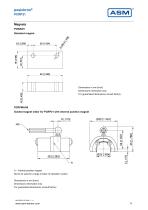
Magnets PCMAG5 Standard magnet Dimensions in mm [inch] Dimensions informative only. For guaranteed dimensions consult factory. PCRPMAG6 Guided magnet slider for PCRP21 with internal position magnet A – Internal position magnet Not to be used for a large number of operation cycles! Dimensions in mm [inch] Dimensions informative only. For guaranteed dimensions consult factory.
Open the catalog to page 11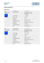
Output specification Analog output U1 Voltage output 0 ... 10 V Excitation current Output voltage Output current Output load Stability (temperature) Reverse polarity, short circuit Output noise Operating temperature Excitation voltage Excitation current Output voltage Output current Output load Stability (temperature) Reverse polarity, short circuit Output noise Operating temperature Excitation voltage
Open the catalog to page 12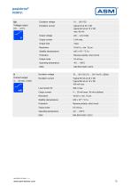
Excitation current Output voltage Output current Output load Stability (temperature) Reverse polarity, short circuit Output noise Operating temperature I1 Current output 4 … 20 mA, 3 wire Excitation voltage Excitation voltage Excitation current Output current Stability (temperature) Reverse polarity, short circuit Output noise Operating temperature
Open the catalog to page 13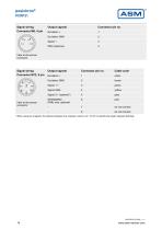
Signal wiring Connector M8, 4 pin Output signals View to the sensor connector Signal wiring Connector M12, 8 pin Cable color SPAN/ZERO (PMU only, optional) View to the sensor connector Output signals * When using two magnets, the distance between the magnets must be min. 70 mm to identify the single magnets definitely.
Open the catalog to page 14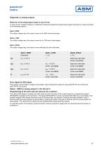
Diagnostic on analog outputs Behaviour of the analog signal output in case of error In case of error (magnet missing or outside the measuring range) the analog output signal will assume a state according to the following options: Alarm_HIGH The output voltage resp. the output current is at HIGH level (overrange). Alarm_LOW The output voltage resp. the output current is at LOW level (underrange). Alarm_HOLD The output voltage resp. the output current will keep the last valid state. keeps last valid state (Order code U1/H) Uout < 0.25 V (Order code U2/U) keeps last valid state (Order code U2/H)...
Open the catalog to page 15All ASM Automation Sensorik Messtechnik GmbH catalogs and technical brochures
 System NMG2
4 Pages
 PTK7
PTK79 Pages
 PTK6
PTK69 Pages
 PTK29
PTK297 Pages
 PTDM7
PTDM78 Pages
 PTAM7
PTAM712 Pages
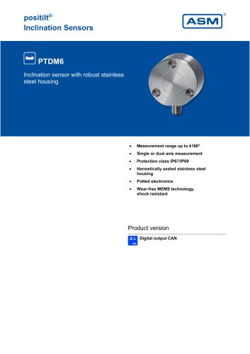 PTDM6
PTDM68 Pages
 PTAM6
PTAM613 Pages
 PTDM5
PTDM510 Pages
 PTAM5
PTAM513 Pages
 PTAM4
PTAM49 Pages
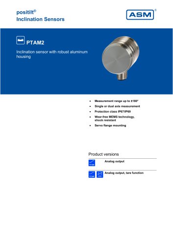 PTAM2
PTAM216 Pages
 PTAM27
9 Pages
 PTM29
PTM2910 Pages
 AWS
AWS5 Pages
 PH68
PH6819 Pages
 PH58
PH5821 Pages
 PH36
PH3621 Pages
 PRAS7
PRAS718 Pages
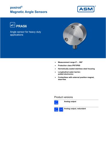 PRAS6
PRAS619 Pages
 PRAS5
PRAS525 Pages
 PRAS4
PRAS48 Pages
 PRAS3
PRAS319 Pages
 PRAS1
PRAS112 Pages
 PRAS29
15 Pages
 PRAS27
16 Pages
 PRAS26
13 Pages
 PRAS20
12 Pages
 PMIB3
PMIB37 Pages
 PMIS3
PMIS38 Pages
 posichron® EasyMount
6 Pages
 PCRP32
18 Pages
 PCST27
26 Pages
 PCST25
27 Pages
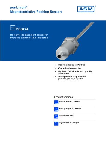 PCST24
29 Pages
 PCQA24
24 Pages
 PCQA22
24 Pages
 PCFP25
22 Pages
 PCFP24
22 Pages
 PCFP23
24 Pages
 WB100M
21 Pages
 WST 21
9 Pages
 WB21
WB2126 Pages
 WST85
WST856 Pages
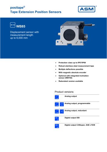 WB85
WB8522 Pages
 WST61
WST616 Pages
 WB61
WB6122 Pages
 WB12
WB1223 Pages
 WB10ZG
20 Pages
 WS7.0
WS7.06 Pages
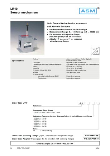 LR19
LR196 Pages
 WS12EX
8 Pages
 WS10EX
8 Pages
 WS58C
WS58C9 Pages
 WS100M
24 Pages
 WS60
WS6012 Pages
 WS7.5
WS7.541 Pages
 WBT21
WBT2111 Pages
 WS21
WS2125 Pages
 WBT61
WBT617 Pages
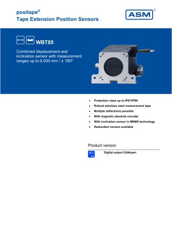 WBT85
WBT857 Pages
 WS85
WS8522 Pages
 WS61
WS6122 Pages
 WS19KT
11 Pages
 WS19KT
16 Pages
 WS17KT
16 Pages
 WS12
WS1239 Pages
 WS10
WS1036 Pages
 WS10ZG
36 Pages
 WS10SG
36 Pages
 WS42C
WS42C8 Pages
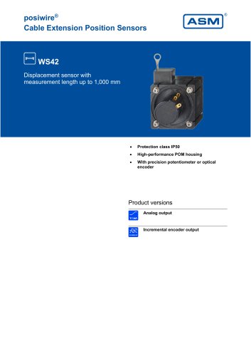 WS42
WS4210 Pages
 WS31C
WS31C8 Pages
 WS31
WS3110 Pages
 PTM27
PTM2710 Pages
 ASM Product Overview
40 Pages



Archived catalogs






- Angular encoder
- ASM incremental encoder
- Measuring machine
- Incremental rotary encoder
- Digital indicator
- Panel panel meter
- ASM inclinometer
- ASM linear position sensor
- Magnetic rotary encoder
- DC rotary encoder
- Linear displacement sensor
- IP67 rotary encoder
- ASM analog position sensor
- ASM digital inclinometer
- Stainless steel rotary encoder
- Optical measurement system
- ASM non-contact position sensor
- ASM 2-axis inclinometer