
- Catalogs
- ASCON TECNOLOGIC
- Process controller with PROFIBUS DP and Mod bus Master/Slave

Process controller with PROFIBUS DP and Mod bus Master/Slave

Process controller with PROFIBUS DP and Mod bus Master/Slave
The document is a user manual for the X5 series process controllers by ASCON spa, designed for industrial environments. These controllers support PROFIBUS DP and Modbus Master/Slave communication protocols and are built for high reliability and functionality. They feature universal input, control alarms, retransmission resources, and adaptive operating modes.
The controllers are available in a 1/8 DIN size (48 x 96 mm) and comply with European Directives for safety and electromagnetic compatibility. They are designed for panel mounting and have a Class II instrument rating.
Installation should be performed by qualified personnel, following safety precautions related to electrical protection and electromagnetic compatibility. The controller must be installed in an enclosure to prevent contact with live parts. The manual provides detailed dimensional drawings and panel cut-out instructions.
The manual outlines the terminal block configuration, wiring precautions, and suggested routing for supply, output, and sensor cables. It includes examples of wiring diagrams for valve control and specifies power supply requirements, including nominal voltage and frequency.
The manual details key functions, data setting, configuration, parameterization, and access levels. It provides instructions for using the setpoint programmer, including program organization, operating conditions, and parameterization.
The document includes technical specifications such as power supply options, output configurations, and communication protocols. It also covers environmental ratings, including operating temperature and humidity ranges.
The controller has no user-serviceable parts and requires specialized equipment for repairs. Technical assistance and repair services are provided by the manufacturer.
The X5 series process controllers are versatile and robust, suitable for various industrial applications. They offer extensive functionality and compliance with international standards, ensuring reliable performance in demanding environments.
The document provides detailed technical specifications and operational guidelines for a PID controller, focusing on tuning methods, input/output configurations, and communication protocols.
- Fuzzy-Tuning: Automatically determines optimal PID terms based on process behavior, suitable when the process variable (PV) is far from the setpoint (SP).
- Continuous Adaptive Tuning: Ideal for processes with changing characteristics, it continuously samples process responses to adjust PID parameters.
- Input Menu: Includes settings for input filters, measure bias, and sampling time to accommodate slow processes.
- Output Menu: Configures control output parameters such as hysteresis, cycle time, and limits for both heating and cooling outputs.
The controller supports Modbus/Jbus and PROFIBUS DP for serial communication, allowing integration with other devices and systems. It offers configurable baud rates and parity settings.
The document outlines access levels and password protection for parameter modification, including calibration and data storage procedures.
- Keypad Commands: Allow setpoint modification, mode selection (auto/manual), and tuning operations.
- Digital Inputs: Configurable for specific functions through the setup procedure.
The document outlines the configuration and operation of digital inputs for controlling various functions. The digital input can activate functions when in the 'On' state and deactivate them when set to 'Off'. This method of activation has higher priority over keypad or serial communication inputs.
Several commands can be executed through digital inputs, such as setting manual mode, locking the keyboard, holding PV measurement, and selecting stored setpoints. The document specifies that the last activated digital input determines the operating setpoint.
The document describes the programmed setpoint feature, which allows up to four programs with 16 segments each. Key characteristics include commands from the keypad, time cycling, and digital outputs related to the program. The program structure consists of initial, normal, and end segments, each with specific purposes and configurations.
If the PV input value exceeds a defined band around the setpoint, the segment time is extended. The band width is a configurable parameter.
The document details options for program behavior after a power failure: continue from the last point, reset to local mode, or continue with a ramp.
Parameters such as program number, segment count, and allowed deviation can be configured. Two digital outputs are available for program purposes.
The status of the program is displayed using LEDs, indicating modes such as run, hold, and end.
Programs can be started or stopped directly via a key or through the parameter menu. The document explains the commands supported during different phases of program execution.
- Resolution and Accuracy: The device features a 12-bit resolution with an accuracy of 0.1%.
- Output Relays: OP3 is an SPDT relay with a normally open contact, supporting 2A/250Vac or 4A/120Vac for resistive loads. OP4 is an SPST relay with similar specifications.
- Analogue/Digital Outputs: OP5 and OP6 (optional) support control or retransmission with analogue outputs ranging from 0/1 to 5V, 0 to 10V, and 0/4 to 20mA. Digital outputs are 0/24Vdc with a 30mA max for solid-state relays.
- Alarms: AL1 to AL4 alarms feature hysteresis from 0 to 5% span, with active high action and various threshold types (deviation, band, absolute).
- Special Functions: Includes sensor break and heater break alarms, with options for latching and blocking.
- Setpoint Configuration: Supports local and remote setpoints with programmable options, including ramps and limits.
- Tuning: Fuzzy-Tuning automatically selects the best method based on process conditions.
- General Characteristics: Features include auto/manual station with bumpless function, programmable setpoints, and safety strategies for out-of-range detection.
- Power Supply: Operates on 100-240Vac or 24Vac/Vdc with compliance to EN61010-1 and CE standards.
- Dimensions and Weight: The device measures 48 x 96 x 110 mm and weighs 380 g max.
- Serial Communication: Optional RS485 isolated communication with Modbus/Jbus and PROFIBUS DP protocols.
The product is warranted to be free from defects in material and workmanship for three years from the date of delivery, excluding failures due to misuse.
Includes icons for various inputs, outputs, and functions such as thermocouples, RTDs, setpoints, and relay types.
Contact information for subsidiaries and distributors in various countries including France, USA, Argentina, Finland, Germany, Greece, Portugal, Spain, Switzerland, Turkey, and the United Kingdom.
Catalog excerpts
proceeding with the installation of to the European Directives. on Directives and Standards used for controller can be found in the file: table with: zip. requires special equipment and specialised on directly by the user. For this purpose, the repair service for its Customers. information. and electromagnetic compatibility are note.
Open the catalog to page 3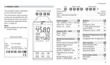
5 1 - Introduction – model Accessories Colour User manual Setpoint C D E F G 0 A 3 5 5 B 1 5 C 0 2nd SSR drive/analogue output (OP6) 4 Options D None 0 6 7 8 Setpoint Programmer [1] E Not fitted 0 4 programs with 16 segments 4 User manual F Italian/English (std.) 0 French/English 1 German/English 2 Spanish/English 3 Front panel colour G Dark (std.) 0 Beige 1 Frequency input 1 Frequency input + OP6 6 1
Open the catalog to page 6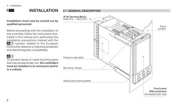
Front panel IP65 protection EN 650529 (IEC 529) Panel surface
Open the catalog to page 7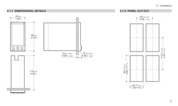
7 2 - Installation PANEL CUT-OUT 65 mm min 2.56 in min 45+0.6 mm 1.78+0.023 in 3.62+0.031 in 113 mm min 4.45 in min
Open the catalog to page 8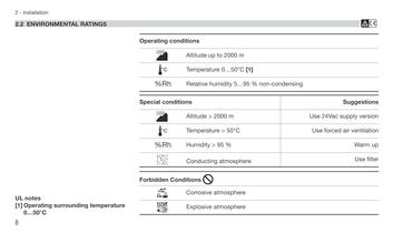
B condensing Use filter Warm up Use forced air ventilation Use 24Vac supply version Suggestions
Open the catalog to page 9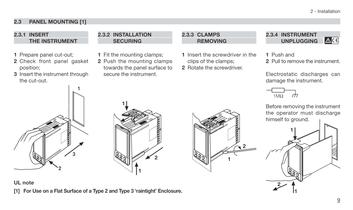
9 2 - Installation the 2.3.4 INSTRUMENT UNPLUGGING B 1 Push and 2 Pull to remove the instrument. Electrostatic discharges can damage the instrument. Before removing the instrument the operator must discharge himself to ground. 1MÙ 2 1 1
Open the catalog to page 10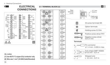
Terminals Cable size 1 mm2 [2] 5.7 mm 0.22 in B 35 screw terminals M3 Option terminals Holding screw 0.5 Nm Positive screw-driver PH1 Negative screw-driver 0.8 x 4 mm Pin connector q 1.4 mm - 0.055 in max. Fork-shape AMP 165004 Ø 5.5 mm - 0.21 in Stripped wire L 5.5 mm - 0.21 in
Open the catalog to page 11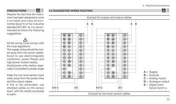
28 27 30 29 26 25 31 32 33 34 35 36 A B 11 3 - Electrical Connections cables cables B A = Supply B = Outputs C = Analog inputs D = Analogue output E = Digital input Serial Comm.s
Open the catalog to page 12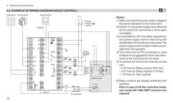
B Notes: Make sure that the power supply voltage is the same indicated on the instrument. Switch on the power supply only after that the electrical connections have been completed. accordance with the safety regulations, the power supply switch shall bring the identification of the relevant instrument. The power supply switch shall be easily accessible from the operator. The instrument is PTC protected. In case failure it is suggested to return the instrument to the manufacturer for repair. protect the instrument internal circuits use: AT fuse for Relay outputs (220 Vac) AT fuse for Relay outputs...
Open the catalog to page 13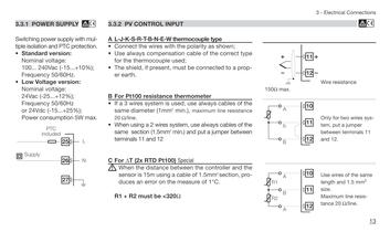
13 3 - Electrical Connections B Wire resistance 150Ù max. Only for two wires system, put a jumper between terminals 11 and 12. Use wires of the same length and 1.5 mm2 size. Maximum line resistance 20 Ù/line. 10 11 12 A B A R2 R1 10 11 12 A b B 11 12
Open the catalog to page 14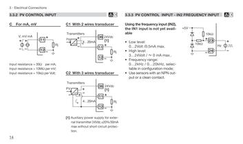
INPUT - IN2 FREQUENCY INPUT B IN2), available selectable mode; output +5V 23 24 10kÙ 10kÙ Hz
Open the catalog to page 15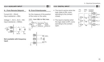
15 3 - Electrical Connections B the corresponding 3 7 6 TTL o.c. Isolated contact Com. IL 3 IL 2 C2 C3 5 NPN o.c. IL 1 C1
Open the catalog to page 16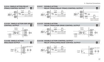
17 3 - Electrical Connections CONTROL OUTPUT B OUTPUT B OUTPUT B Fuse Coil of the cool load contactor 32 33 OP2 [1] Cool load Static Relay 8 9 OP5 8 9 Cool OP5 load mA mV,V
Open the catalog to page 18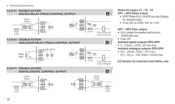
Notes for pages 17 - 18 - 19 - OP2 Relay output SPST Relay N.O., 2A/250 Vac (4A/120Vac) for resistive load, Fuse 2AT at 250V, 4AT at 110V. - OP2 Triac output O. contact for resistive load of up to 1A/250 Vac max. Fuse 1AT Isolated digital outputs OP5-OP6 0…24Vdc, ±20%, 30 mA max. Isolated analogue outputs OP5-OP6 4…20mA, 750Ù / 15V max. 1…5V, 0…10V, 500Ù / 20mA max. Varistor for inductive load 24Vac only
Open the catalog to page 19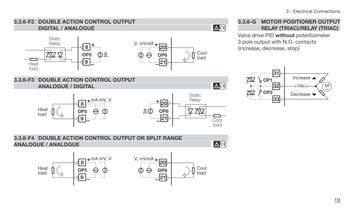
19 3 - Electrical Connections 3.3.6-G MOTOR POSITIONER OUTPUT RELAY (TRIAC)/RELAY (TRIAC) Valve drive PID without potentiometer pole output with N.O. contacts increase, decrease, stop) OP1 33 32 31 OP2 Vac Decrease Increase M~
Open the catalog to page 20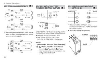
SERIAL COMMUNICATIONS (OPTION) [2] B Galvanic isolation 500Vac/1 min; Compliance to the EIA RS485 standard Modbus/Jbus; Termination setting dip switches. C C MASTER SLAVE 1 2 3 13 14 15 1 2 3 4 MASTER SLAVE
Open the catalog to page 21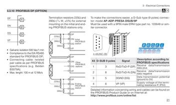
B 21 3 - Electrical Connections concerning wiring and cables can be found on Guide or on Internet at: online/list 33 easier, a D-Sub type (9 poles) connector: PRESA-DSUB/9P male ERNI type part no. 103648 or similar Signal Description according to PROFIBUS specifications TxD-P (DP) Receive data/transmission data plus TxD-N (DN) Receive data/transmission data negative VP) (DG) Data transmission potential (ground to 5V) Supply voltage of the terminating resistance-P, (P5V)
Open the catalog to page 22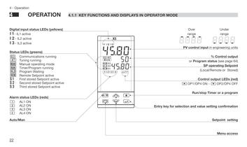
MODE Over range Under range SP operating Setpoint (Local/Remote or Stored) % Control output or Program status (see page 64) Control output LEDs (red) åOP1/OP4 ON - çOP2/OP4 OFF Run/stop Timer or a program selection and value setting confirmation Setpoint setting Menu access 8_8_8_8_ -8-8-8-8 PV control input in engineering units
Open the catalog to page 23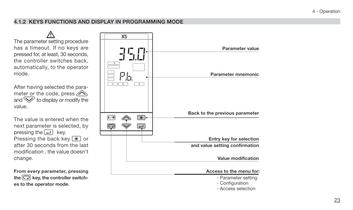
23 4 - Operation value mnemonic parameter selection confirmation modification menu for: setting selection
Open the catalog to page 24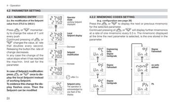
SETTING page 26) display the next or previous mnemonic or %will display further mnemonics every 0.5 s. The mnemonic displayed parameter is selected, is the one stored in the Unit °f Unit none Unit ph Degree Fahrenheit no units defined Ph
Open the catalog to page 25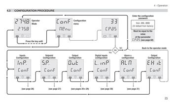
25 4 - Operation EHit ALM Conf Conf (see page 31) Back to the operator mode Enter the configuration password Must be equal to the value of the parameter C.Pas (see page.50) from -999...9999 (33 default from factory) Alarm s configuration Output Configuration
Open the catalog to page 26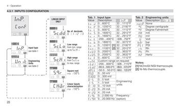
Hertz ph Hz PInp . 1112°F request Engineering 122.0°F 572.0°F 1112°F 752°F 2912°F 2912°F 2192°F 1112°F Value Description éUnit Tab. 2 Engineering units none None rh °C Degree centigrade °f Degree Fahrenheit Rh MA mA MU mV U Volt Ph bar bar psI PSI Frequency 3272°F 2192°F 1112°F 3632°F 3632°F 2012°F Notes: [1] NiChroSil-NiSil thermocouple. [2] Ni-Mo thermocouple.
Open the catalog to page 27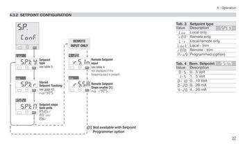
27 4 - Operation Tab. 4 Rem. Setpoint Value Description 0=5 0…5 Volt 1=5 1…5 Volt 0=20 0…20 mA Tab. 3 4=20 4…20 mA Setpoint type 0=10 reM.t Remote - trim 0…10 Volt érs.In loc.t Local - trim l=r Local/remote only reM Remote only loc Local only Value Description éS.P.ty Prog Programmed (option)
Open the catalog to page 28All ASCON TECNOLOGIC catalogs and technical brochures
 REFRIGERATION CATALOGUE 2020
85 Pages
 NP4
NP42 Pages
 KR1E
KR1E4 Pages
 at on cloud
8 Pages
 Sensitive Touch - Data sheet
4 Pages
 Z31/Y39 - Data sheet
4 Pages
 ASCOMB - Technical bulletin
12 Pages
 TCPDE M
2 Pages
 Sensitive Touch
4 Pages
 opmt
opmt2 Pages
 MP02
MP022 Pages
 Loop_components_catalogue_2015
49 Pages
 Deltadue series
8 Pages
 Gammadue series
8 Pages
 IO-CB series
4 Pages
 Climatic test chambers.
2 Pages
 Paperless recorder
4 Pages
 Industrial operator panel
2 Pages


Archived catalogs
 m81
m816 Pages
 Refrigeration catalogue 2016
168 Pages
 CATALOGO PRODOTTI 2014/2015
113 Pages
 ClimaPAC
8 Pages
 VA7810 Series Self-Calibrating
10 Pages
 ZIS EIIRLIBGPMAT2018
1 Page
 Pneumatic Actuators
7 Pages
 TRH21
TRH214 Pages
 TRH52
TRH524 Pages
 TRH-MINI
3 Pages


