- Catalogs
- AS ENERGI GLOBAL LLC
- Thyristor - Diode Modules MFC600 MFA600 MFK600 MFX600
Thyristor - Diode Modules MFC600 MFA600 MFK600 MFX600
1 /3Pages

Thyristor - Diode Modules MFC600 MFA600 MFK600 MFX600
1 /3Pages
Catalog excerpts
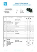
Thyristor - Diode Modules MFC600 MFA600 MFK600 MFX600 Features: Isolated mounting base 2500V~ Pressure contact technology with IT(AV) VDRM/VRRM ITSM I2t Incrtased power cycling capability Space and weight savings AC/DC Motor drives Various rectifiers VALUE SYMBOL TEST CONDITIONS 180 half sine wave 50Hz Single side cooled,Tc=85C Mean on-state current VDRM VRRM Repetitive peak off-state voltage Repetitive peak reverse voltage VDRM&VRRM tp=10ms VDsM&VRsM= VDRM&VRRM+100V respectively IDRM IRRM Repetitive peak current Surge on-state current 10ms half sine wave VR=60%VRRM On-state slop resistance Peak on-state voltage Critical rate of rise of off-state voltage Critical rate of rise of on-state current Gate source 1.5A tr ≤0.5μs Repetitive Gate trigger current Gate trigger voltage IH VGD Rth(j-c) Rth(c-h) Viso Fm Holding current Non-trigger gate voltage Thermal resistance Junction to case Thermal resistance case to heatsink Isolation voltage Single side cooled Single side cooled Stored temperature
Open the catalog to page 1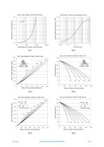
MTC600/1800V Peak On-state Voltage Vs.Peak On-state Current Max. junction To case0.054 Thermai Impedance Vs.Time 0.06 Transient thermal impedance,°C/W Iinstantaneous on-state voltage,volts Fig.2 Max. case Temperature Vs.Mean On-state Current MT600/1800v MTC600/1800V Max. Power Dissipation Vs.Mean On-state Current Conduction Angle Conduction Angle Fig.4 Max. case Temperature Vs.Mean On-state Current MTC600/1800 Max. Power Dissipation Vs.Mean On-state Current MTC600/1800V 700 Conduction Angle Case temperature°C Conduction Angle
Open the catalog to page 2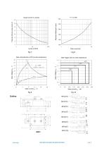
Surge Current 16 Vs.Cycles Total peak half-sine surge current,kA Fig.8 Gate Trigger Zone at varies temperature 3 V,200MA 4.5 Gate characteristic at 25°C junction temperature 18
Open the catalog to page 3All AS ENERGI GLOBAL LLC catalogs and technical brochures
 MFC200 MFA200 MFK200 MFX200
3 Pages
 QL5-QL50
2 Pages
 SKT 10
5 Pages
 AMDD89N12K
8 Pages
 MDS50
MDS503 Pages


