- Catalogs
- AS ENERGI GLOBAL LLC
- Thyristor - Diode Modules MFC55 MFA55 MFK55 MFX55
Thyristor - Diode Modules MFC55 MFA55 MFK55 MFX55
1 /3Pages

Thyristor - Diode Modules MFC55 MFA55 MFK55 MFX55
1 /3Pages
Catalog excerpts
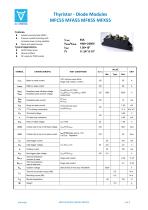
Thyristor - Diode Modules MFC55 MFA55 MFK55 MFX55 Features: Isolated mounting base 3000V~ Pressure contact technology with Increased power cycling capability Space and weight savings AC/DC Motor drives Various rectifiers IT(AV) VDRM/VRRM ITSM I2t VALUE SYMBOL TEST CONDITIONS 180 half sine wave 50Hz Single side cooled, Tc=85C Mean on-state current VDRM VRRM Repetitive peak off-state voltage Repetitive peak reverse voltage VDRM&VRRM tp=10ms VDSM&VRSM= VDRM&VRRM+100V respectively IDRM IRRM Repetitive peak current Surge on-state current 10ms half sine wave VR=60%VRRM On-state slop resistance Peak on-state voltage Critical rate of rise of off-state voltage Critical rate of rise of on-state current Gate trigger current Gate trigger voltage IH VGD Rth(j-c) Rth(c-h) Viso Fm Holding current Non-trigger gate voltage Thermal resistance Junction to case Thermal resistance case to heat sink Isolation voltage Single side cooled Single side cooled Thermal connection torque (M5) Stored temperature
Open the catalog to page 1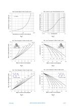
Max . junction To case Thermai Impedance Vs.Time 0.49 MTC55/2500V Peak On-state Voltage Vs.Peak On-state Current 0.5 Transient thermal impedance,°C/W Iinstantaneous on-state voltage,volts 100 Instantaneous on-state currant,amperes Max . case Temperature Vs.Mean MTC55 高压 On-state Current MTC55高压 Max . Pow er Dissipation Vs.Mean On-state Current Conduction Angle Case temperature,°C Mean on-state current,amperes Fig.4 Max . case Temperature Vs.Mean On-state Current MTC55高压 MTC55高压 Max . Pow er Dissipation Vs.Mean On-state Current 140 Conduction Angle Conduction Angle Conduction Angle
Open the catalog to page 2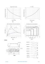
Surge Current 1.5 Vs.Cycles Total peak half-sine surge current,kA Gate characteristic at 25°C junction temperature Gate Trigger Zone at varies temperature 2.5V,100MA MFK(DT) MFX(DT)
Open the catalog to page 3All AS ENERGI GLOBAL LLC catalogs and technical brochures
 MFC200 MFA200 MFK200 MFX200
3 Pages
 QL5-QL50
2 Pages
 SKT 10
5 Pages
 AMDD89N12K
8 Pages
 MDS50
MDS503 Pages


