LIV100
1 /29Pages

LIV100
1 /29Pages
Catalog excerpts

LIV Laser Diode Characterization System High throughput Pre-packaging laser diode testing Pulse duration Production quality assurance Maximum current Current rise time The LIV100 laser diode measurement system is a µC-controlled autonomous system comprising an analogue-digital signal processing unit (ADSPU), current driver and an integrating sphere. The LIV measurement consists of pulsing the laser diode with a specific current and measuring the output light power (L) via the integrating sphere - photodiode transimpedance amplifier combination and also the voltage drop (V) across the laser diode. The current is then increased by a fixed amount and the measurement repeated. This is repeated many times to produce a staircase increase in current and measurements of L and V for each current. The data are subsequently used to generate L/I and V/I curves giving specific information about the quality of the laser diode under test. The LIV100 has been designed for testing laser diodes at the chip or bar level prior to packaging. Thus the manufacturer can determine the quality of the individual laser diodes before spending the time and resources on packaging defective or deficient diodes. Since proper temperature control cannot be realized on the naked laser diode chips, the LIV100 performs all tests using current pulses as short as 150ns in duration. This avoids any significant thermal loading which may affect results. Artifex Engineering Dortmunder Str. 16-18 26723 Emden, Germany mail: [email protected] http://www.afx-eng.com
Open the catalog to page 1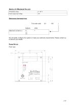
ABSOLUTE MAXIMUM VALUES Temperature range Power supply input voltage ORDERING INFORMATION Full order code: Options Maximum current (c): We will gladly configure the system to meet your particular requirements. Please contact us to discuss your details. CASE STYLE Front view:
Open the catalog to page 2
Back view:
Open the catalog to page 3
SPECIFICATIONS PARAMETER INPUT Sampling rate Photodiode transimpedance amplifier gain Input capacitance <20pF, gain = 1 k Optimum gain determined automatically Transimpedance amplifier rise 1 time OUTPUT Pulse duration Current overshoot Pulse separation Current range SIGNAL PROCESSING SRAM depth of storage (large data set) 2 Number of measurement 4 channels Number of measurement cycles for averaging Transfer rate POWER SUPPLY Voltage With optimized current transmission line. At large sample sizes within the pulse, this minimum value may not be realized. See pages 10 and 13 for details. 4 Fixed...
Open the catalog to page 4
TYPICAL PERFORMANCE DATA Flatness Current Linearity
Open the catalog to page 5
Measurement time including parameter upload and data download: Approximate Duration5 [ms] 128 current steps, 1µs pulse duration, 0.1% duty cycle, no averaging 128 current steps, 10µs pulse duration, 1% duty cycle, no averaging 128 current steps, 1µs pulse duration, 0.1% duty cycle, averaging over 16 sequences 128 current steps, 10µs pulse duration, 1% duty cycle, averaging over 16 sequences Dependant on host computer configuration and demands. 6 /29
Open the catalog to page 6
PRINCIPLES OF OPERATION The LIV measurement is the concurrent measurement of light power (L), current (I) and voltage (V) from laser diodes or laser diode arrays during the fabrication process. A laser diode array consists of a 1xN array of single laser diodes. Each diode in an array can be tested separately or the full array at once, depending on the configuration of the electrode contacting and the integrating sphere. The LIV100 system comprises an analog-digital signal processing unit, current driver, current transmission system and an integrating sphere. The complete system is depicted as...
Open the catalog to page 7
The LIV measurement consists of pulsing the DUT (laser diode) with a specific current and measuring the output light power (L) via the integrating sphere-photodiode-transimpedance amplifier combination and also the voltage drop (V) across the laser diode. The current is then increased by a fixed amount and the measurement repeated. This is repeated many times to produce a staircase increase in current and measurements of L and V for each current. The data will subsequently be used to generate L/I and V/I curves giving specific information about the quality of the laser diode under test. Since...
Open the catalog to page 8
MEASUREMENT SEQUENCE A measurement sequence involves setting a minimum and maximum current level, as well as a current step size. This results in a staircase of current pulses with measurements of the selected laser parameter (light power, voltage and current) at each pulse. AVERAGING METHOD In order to improve signal to noise ratio (at the cost of measurement time), the measurement sequence may be automatically repeated up to 250 times and the results averaged. This is relevant for the small data set only (see "Data Set"). Parallel (a=0): each current is pulsed “m” times before setting the next...
Open the catalog to page 9
DATA SET Two types of data set are available. Large Data Set (t=1) (Oscilloscope mode) The full, raw data set of each sample measured is downloaded to the host computer. This measurement provides full information on each active channel equivalent to a digital sampling oscilloscope operating at the sampling frequency selected in the paramter upload. This mode of operation is useful in the initial setting up of a new measurement environment, or new line of laser diodes or for debugging a setup. This mode is not recommended for on-line quality assurance as the throughput is low due to the time required...
Open the catalog to page 10
number of samples in a recorded pulse (L) number of measured channels (M) zero (place holder), Photodiode #1 gain code (0..2) Photodiode #2 gain code (0..2) zero (place holder) pulse separation flag signed 16 bit integer, little endian7 signed 16 bit integer, little endian signed 16 bit integer, little endian signed 16 bit integer, little endian signed 16 bit integer, little endian signed 16 bit integer, little endian signed 16 bit integer, little endian signed 16 bit integer, little endian signed 16 bit integer, little endian signed 16 bit integer, little endian There is a timeout for sending...
Open the catalog to page 11All Artifex Engineering e.K. catalogs and technical brochures
 Q-Switch Pockels Cells
7 Pages
 LDD100
8 Pages
 LGM100
4 Pages
 LIV110_REV5C
10 Pages
 TZA600
9 Pages
 LDM300
5 Pages
 IRS100 2009
5 Pages
 TZA500
35 Pages
 TZA400
12 Pages
 TZA300
12 Pages
 OPM500
39 Pages
 OPM400
10 Pages
 OPM300
15 Pages
 OPM200
9 Pages
 Filters
1 Page
 OPM100
6 Pages
 Gated Integrating Amplifier
12 Pages
 EO Q-Switches BBO
4 Pages
 EO Q-Switch KD*P
3 Pages
 Optical Flats
4 Pages
 Laser Diode Modules LDM200
4 Pages
 Optical Power Monitor OPM150
34 Pages


- Glass lens element
- Camera objective
- Spectrum lens element
- Measuring amplifier
- Optical prism
- Electronic amplifier
- Visible lens element
- Machine vision lens
- Glass prism
- Fixed-focus camera objective
- Current amplifier
- Machine vision camera objective
- Beam splitter
- Concave array lens element
- Polarizer
- Fused silica prism
- Plastic lens element
- Achromatic lens element
- Optical beam splitter
- Doublet lens element