- Catalogs
- Artifex Engineering e.K.
- Gated Integrating Amplifier GIA100
Gated Integrating Amplifier GIA100
1 /12Pages

Gated Integrating Amplifier GIA100
1 /12Pages
Catalog excerpts

Optoelectronics & Engineering Services Gated Integrating Amplifier HIGHLIGHTS • Fast switching • Sensitive photodiode preamplification • Fast settling • Optical pulse energy measurement integrating analogue • Signal recovery • Dimensions (2 channel unit) MEASUREMENT PRINCIPLE The GIA100 series of gated integrating amplifiers employ dual monolithic switched integrators. This design results in very low leakage error, charge injection error and pickup. The precision input stage may be configured for current or voltage inputs. The GIA100 series of gated integrators is useful for signal processing in a wide range of applications such as photodiode monitoring and time domain signal analysis. The output is a voltage linearly proportional to the integral of the input during a period of time set by a TTLcompatible gate. Between gates, the output is held constant for readout or digital conversion via an external A/Dconverter or I/O-card (not included). Artifex Engineering Dortmunder Str. 16-18 26723 Emden, Germany The fast response time at high signalnoise-ratio makes the GIA100 series particularly useful in online production control. The GIA100 series is insensitive to electromagnetic interference by design, an important factor when working in „dirty“ industrial environments. The case wings provide for mounting on standard 25mm and 1“ optical table tops and for OEM applications. 19“ rack mounting is also available. Reset Integrate/Hold mail: [email protected] http://www.afx-eng.com
Open the catalog to page 1
ABSOLUTE MAXIMUM RATINGS Current Input Voltage Input Average input Temperature Range ORDERING INFORMATION Order code: Options Case style OEM style with gullwing mounts For example, a 2 channel, OEM style unit with current input (for example for photodiode measurement) would be ordered as: GIA100GI2 For 19“ rack systems or mixed systems (mixed amplifiers or receptacles), please contact us.
Open the catalog to page 2
SPECIFICATIONS Current Input Parameter Voltage Input Input Range (Min=noise equivalent input, Max=full scale) Output Range (full scale) Linear analogue scale = V ∫ I dt out 100 pF in Output scale Linear analogue Output impedance Logic Switching time (integrate / hold, reset, gain) Power Supply Type Wall plug (supplied) Dimensions Dimensions * Identical values as for current input version 1 Adapters for other connector systems available.
Open the catalog to page 3
CASE STYLES
Open the catalog to page 4
PERFORMANCE Output (4µs integration time) lower trace: 2 VDC input upper trace: GIA output (1.5 V) held for 400 µs following 4 µs integration upper trace: as previous 4x expanded vertical scale Gain Switching Dead Time low sensitivity → high sensitivity high sensitivity → low sensitivity control voltage
Open the catalog to page 5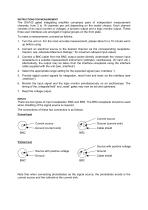
INSTRUCTIONS FOR MEASUREMENT The GIA100 gated integrating amplifier comprises pairs of independent measurement channels, from 2 to 16 channels per unit depending on the model chosen. Each channel consists of an input (current or voltage), a function output and a logic monitor output. These three user interfaces are arranged in logical groups on the front plate. To make a measurement, proceed as follows: 1. Turn the unit on. For the most accurate measurement, please allow for a 15 minute warm up before using. 2. Connect an electrical source to the desired channel via the corresponding receptacle....
Open the catalog to page 6
OUTPUTS The analogue output is provided via standard BNC sockets as well as through the interface. The output is a voltage linearly proportional to the integral of the input during a period of time set by a TTL-compatible gate. Between gates, the output is held constant for readout or digital conversion via an external A/D-converter or I/O-card (not included). INDICATORS The interface provides an additional power indicator, useful for automated operation: Pin 19: +5 V = power on 0 V (analogue ground) = power off
Open the catalog to page 7
LOGIC Logic control is via the DB37 interface. This instrument uses +5 V / 0 V (= analogue ground) logic, which may be TTL2. The pin assignment is described under „Interface“. Function Integrate / Hold The status of the logic for each channel may be monitored by connecting the corresponding BNC logic monitor socket to an oscilloscope. This output is HI during „reset“ and „integrate“ and is LO at all other times. This is useful for setting the gate positions and durations. A typical measurement begins by resetting the channel in question by setting the „reset“ wire LO for a minimum of 25 µs, in...
Open the catalog to page 8
Note that when using the GIA100 for photodiode monitoring, the photodiode itself will store charge during the time between the end of the reset period and the beginning of the integration period. Thus, for photodiode monitoring purposes, the effective integration time is from the end of the reset period to the end of the integration period. The only restriction here is that the voltage on the photodiode due to the charge stored during the time between the end of the reset period and the beginning of the integration period should be kept below 500mV. For example, a photodiode with a capacitance...
Open the catalog to page 9
LOGIC MONITOR The status of the logic for each channel may be monitored by connecting the corresponding BNC-socket to an oscilloscope. This output is: HI during „reset“ and „integrate“ LO at all other times. This is useful for setting the gate positions and durations. DAMAGE The unit may be damaged by exceeding the maximum average inputs. Please read „Absolute Maximum Ratings“ for these maximum values before working with the instrument. Use only the power supply and power supply cable provided with the unit. INTERFACE The interface on the back panel allows readout of the measurement values, as...
Open the catalog to page 10
TROUBLE SHOOTING In the event that a measurement is not successful, the following possibilities should be analysed: Symptom Possible Errors • Ensure the power cord is connected at both ends and switch the system on. • Fuse blown • Secondary, internal self resetting fuses, only. In the event that a secondary fuse „blows“, shut off the power, correct the fault and wait a few minutes before switching the power back on. • Switch to more sensitive range or increase input • Switch to a less sensitive range or lower the input No output and power LED is on Output at full scale, independant of input In...
Open the catalog to page 11All Artifex Engineering e.K. catalogs and technical brochures
 Q-Switch Pockels Cells
7 Pages
 LDD100
8 Pages
 LGM100
4 Pages
 LIV100
29 Pages
 LIV110_REV5C
10 Pages
 TZA600
9 Pages
 LDM300
5 Pages
 IRS100 2009
5 Pages
 TZA500
35 Pages
 TZA400
12 Pages
 TZA300
12 Pages
 OPM500
39 Pages
 OPM400
10 Pages
 OPM300
15 Pages
 OPM200
9 Pages
 Filters
1 Page
 OPM100
6 Pages
 Gated Integrating Amplifier
12 Pages
 EO Q-Switches BBO
4 Pages
 EO Q-Switch KD*P
3 Pages
 Optical Flats
4 Pages
 Laser Diode Modules LDM200
4 Pages
 Optical Power Monitor OPM150
34 Pages


- Glass lens element
- Camera objective
- Spectrum lens element
- Measuring amplifier
- Optical prism
- Electronic amplifier
- Visible lens element
- Machine vision lens
- Glass prism
- Fixed-focus camera objective
- Current amplifier
- Machine vision camera objective
- Beam splitter
- Concave array lens element
- Polarizer
- Fused silica prism
- Plastic lens element
- Achromatic lens element
- Optical beam splitter
- Doublet lens element