Overview: The document provides a comprehensive overview of ARNO® tools, focusing on parting-off and grooving systems. It includes specifications for various tool holders, modules, and systems designed for precision machining tasks.
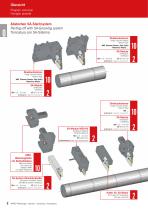
Specifications: The document details specifications for SA and SE systems, including module dimensions (EB and ET), design orientations (R/L), and compatibility with different machine types (e.g., BMT, VDI). It also covers the dimensions and configurations of NC-Groove turning systems and other specialized tools.
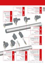
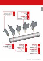
Tool Holders and Modules: Various tool holders are described, including flange-mounted holders, monoblock holders, and those with internal coolant systems. The document specifies the use of KMH tool-holders with coolant jets and the availability of polygon-shank tool holders on request.
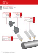
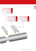
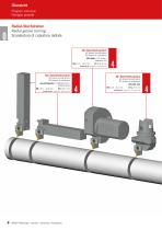
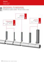
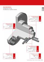
Grooving Systems: The document outlines the capabilities of NC-Groove turning systems, including straight and cranked designs, and their applications in radial and axial groove turning. It also highlights the Clip-Groove® and SHORT-Cut® systems for specific grooving tasks.
Special Solutions: ARNO® offers customized solutions tailored to specific applications, emphasizing the adaptability of their tools to meet unique machining requirements.
Key Features: The document emphasizes the importance of internal cooling systems (ACS) in enhancing tool performance and longevity. It also highlights the versatility of the tools in handling various machining tasks, such as threading, chamfering, and copying.
Overview of ARNO Grooving Systems: ARNO offers a versatile range of grooving systems designed for various applications, including radial and axial grooving, parting-off, and copy turning. The systems are modular, allowing for different tool variants by changing the support blade and clamp. This flexibility enables efficient chip removal in all three main cutting directions.
Key Systems and Features:- GROOVE: A form grooving system with 3-edged inserts for radial or axial applications.
- SA Grooving System: Solutions for part-off and grooving up to 140 mm diameter with various tooling designs.
- SE Grooving System: Monoblock holders for double-sided inserts suitable for grooving, part-off, and copy turning.
- ATS Grooving System: Designed for parting-off and grooving, profile grooving, or copy turning, featuring a T-shaped indexable insert with 3 cutting edges.
- PROFIL-CUT: A system for creating customer-specific grooves in one plunge.
- ARNO Mini-System: A modular boring system starting at a minimum diameter of 0.7 mm with a maximum reach of 50 mm.
Service and Support: ARNO provides personalized service with a dedicated contact for optimizing production processes. They offer fast delivery, with orders placed by 18:00 CET (16:00 on Fridays) delivered the next working day, subject to stock availability. ARNO emphasizes long-term customer relationships and efficient production processes.
Global Presence: ARNO has a global presence with subsidiaries and distributors worldwide, ensuring easy access to their tools and services.
Technical Specifications:- Groove width precision: ± 0.02 mm
- Cutting depths up to 6.5 mm
- Available in various shapes and sizes
- VDI shank for enhanced process reliability
- Optimized coolant supply for reliable processes
Specifications: The document provides detailed specifications for various cutting tools and materials. It includes dimensions, material types, and recommended cutting speeds. The tools are categorized by their main and secondary applications, with specifications such as groove width and shank sizes.
Procedures: The document outlines procedures for selecting and using different types of cutting tools, including monoblock holders, blades, and modules. It emphasizes the importance of accurate insert positioning and the benefits of using double-edged inserts for high productivity.
Standards and Recommendations: Recommended cutting data is provided for various materials, including unalloyed steel, stainless steel, cast iron, aluminum alloys, and non-metallic materials. The document suggests adjusting these values based on specific machining applications.
Key Features: The document highlights the features of the ARNO®-Werkzeuge grooving system, such as the ACS cooling system, which enhances tool life by reducing wear and improving chip removal. It also mentions the cost-efficiency and reliability of directly pressed inserts with dedicated geometries.
Tables and Data: The document includes tables with cutting speeds and material properties, such as Brinell hardness and tensile strength, for different material groups. These tables serve as a reference for selecting appropriate cutting parameters.
Conclusion: The document serves as a comprehensive guide for selecting and using ARNO®-Werkzeuge cutting tools, providing detailed specifications, recommended procedures, and cutting data to ensure optimal performance and tool longevity.
Introduction to ARNO Cooling System (ACS): The ARNO Cooling System (ACS) is a patented technology designed to enhance the efficiency of parting off, grooving, and groove turning operations. It is particularly effective with the SA and SE grooving systems. The system utilizes advanced cooling techniques to improve tool life and process reliability.
Specifications and Features: The ACS system is available in two variations: ACS1 and ACS2. ACS1 features a single coolant hole that directs coolant along the insert seat, exiting at the cutting zone to efficiently remove swarf and reduce wear. ACS2 includes an additional coolant hole that cools the tool flank from underneath, further enhancing tool life and cutting performance.
Benefits of ACS Technology:- Significant increase in tool life, averaging 300% longer due to reduced wear.
- Optimized chip breakage and precise chip removal through effective chip flushing.
- Precise coolant feed eliminates the need for adjustments, reducing potential errors.
- Higher cutting parameters and improved surface quality due to effective cooling.
Innovative Manufacturing: The ACS system benefits from additive manufacturing, allowing for the integration of two coolant holes in narrow modules. The bottom hole ends in a triangular shape, ensuring coolant reaches the edge of the tool flank.
System Introduction and Market Position: ARNO's ACS system addresses common issues with existing cooling methods, such as inefficiency and poor swarf evacuation in deep grooves. By directing coolant directly through the insert seat, the ACS system provides superior cooling and cutting conditions, reducing the risk of build-up edges and cutting edge breakouts.
ARNO Services: ARNO offers comprehensive services, including design, production, and distribution under one roof. With 95% of standard products available from stock, orders placed before 18:00 CET are dispatched the same day. ARNO's technical sales engineers provide on-site support to ensure optimal product performance.
Conclusion: The ARNO Cooling System (ACS) represents a significant advancement in machining technology, offering unmatched cooling efficiency and productivity enhancements. Its innovative design and manufacturing process make it a leading choice for parting off and grooving applications.
Introduction to ARNO-ACS Cooling System: The ARNO-ACS Cooling System is designed for double-sided inserts with groove widths ranging from 1.5 to 10mm and groove depths up to 105mm. It offers nine carbide grades and six chip breakers, including inserts with a 15° angle, providing solutions for nearly all materials. The system ensures maximum performance by cooling the cutting edge effectively and guiding chips out of grooves, even in deep cuts.
Key Benefits:- Reduces build-up edge and thermal cracking by avoiding thermal shocks.
- Improves chip control and breaking.
- Provides excellent surface finish and flatness.
- Nickel-plated holders protect against corrosion.
- Reduces setup time as there is no need for adjusting coolant jets.
Performance and Productivity: In practical tests, the ARNO-ACS system significantly increased tool life and productivity. For example, in cutting trials with stainless steel, productivity increased by over 100%, and with aluminum-magnesium alloys, productivity increased by around 300%.
Tool and Holder Options: The document details various tool shank options, inserts, and monoblock holders suitable for different applications, including sliding head auto lathes and Traub TNL12 machines. The designation system for tools and inserts is explained, covering aspects like groove width, insert length, and connection types.
Conclusion: The ARNO-ACS Cooling System is a patented technology that enhances tool life and machining efficiency through innovative cooling techniques, making it a valuable solution for high-performance cutting operations.
Specifications: The document provides detailed specifications for tool holders and modules used in machining processes. It includes dimensions in millimeters and outlines the compatibility of various components such as the KMH holder and SA modules. The coolant supply is ensured within the adjustment range, and dimensions like 'AKL' change accordingly.
Spare Parts: A list of spare parts is provided, including holders, screws, and keys. Specific part numbers are mentioned for different configurations of tool holders and modules.
Assembly Options: The document describes normal and upside-down assembly options for tool holders. It also provides guidance on selecting the appropriate KMH holder and module type from tables provided in the document.
Handling Instructions: Instructions are given for selecting the correct KMH holder and module type based on the tables provided. The document also notes that certain holders are supplied without modules.
Tables and Data: Several tables are included, detailing the dimensions and specifications of various tool holders and modules. These tables provide critical information for selecting the appropriate components for specific machining tasks.
Additional Coolant Options: Information is provided on additional coolant options, including part numbers for external coolant jets.
Remarks: Assembly instructions are referenced to be found on specific pages, and it is noted that certain keys are not included in the delivery.
Specifications: The document provides detailed specifications for ARNO® tools, focusing on grooving and cutting tools. It includes various models such as MSA-IL/R-SA1602 and MSA-IL/R-SA2402, with dimensions and maximum diameters specified for solid materials and pipes. The tools are designed with through-tool coolant systems (ACS2-3D) and are compatible with specific flange-mounted holders mentioned in chapter 10.
Procedures: Instructions for selecting suitable holders and inserts are provided, emphasizing compatibility with Tornos, Göltenbodt, and Index systems. The document also outlines the use of spare parts like screws and keys, with part numbers for easy identification.
Standards and Recommendations: The document highlights the importance of using the correct geometry for different materials, such as high-positive geometries for aluminum and non-ferrous metals, and specific geometries for stainless steels. It recommends using certain grades for specific applications, ensuring optimal performance and tool life.
Geometries and Grades: Detailed descriptions of geometries (e.g., -ALU, -FM, -F1) and their applications are provided, focusing on cutting properties, chip control, and material compatibility. The document also describes various grades (e.g., AK1015, AN1015) with their wear resistance and toughness, suitable for different materials and cutting speeds.
Key Data from Tables and Charts: The tables list tool dimensions, maximum diameters, and compatible inserts. Charts illustrate the relationship between cutting forces and tool geometries, providing visual guidance for selecting the appropriate tool for specific applications.
Critical Information: Emphasis is placed on selecting the correct tool geometry and grade for the material being machined to ensure efficiency and longevity. The document also stresses the importance of using compatible holders and spare parts to maintain tool performance.
Introduction to ARNO-ACS Cooling System: The ARNO-ACS cooling system is designed for the SE (grooving and groove turning) program, offering a unique solution that directs coolant through the insert seat directly to the cutting edge. This system is distinguished by its ability to deliver coolant without obstruction, enhancing cooling efficiency at the cutting zone.
Advantages of the ARNO-ACS Cooling System:- Enables maximum speed and feed rates.
- Reduces build-up edge and thermal cracking by preventing thermal shocks.
- Ensures controlled chip breaking and superb surface finish.
- Provides excellent flatness and corrosion protection due to nickel-plated holders.
- Reduces setup time as there is no need to adjust coolant jets.
Specifications: The system supports double-sided inserts with groove widths from 2 to 6 mm and groove depths of 12 and 21 mm. It offers six carbide grades and five chip breaker geometries, including options with a 15° angle, suitable for a wide range of materials.
Tool and Holder Options: Monoblock holders are available for both 12 mm and 21 mm groove depths. These holders are designed for use with the ACS cooling system and are available in various configurations to suit different machine setups.
Designation System: The designation system for ARNO tools includes codes for application area, cooling system type, insert length, holder type, groove width, and other parameters, allowing for precise tool selection based on specific machining requirements.
Accessories and Spare Parts: Various accessories such as coolant supply fittings and spare parts like screws and keys are available to support the ARNO-ACS system. Custom coolant inlet specifications can be accommodated upon request.
Overview: This document provides detailed specifications and descriptions of various machining tools and accessories, focusing on external and internal groove turning. It includes information on tool holders, inserts, and spare parts, with dimensions and configurations for different machining needs.
Specifications: The document lists multiple tool models with specific dimensions such as length, height, and diameter. Each tool is designated with a unique code, indicating its size and compatibility with different machining operations. The tools are categorized based on their application, such as radial groove turning and axial groove turning.
Procedures: The document outlines the use of basic holders and accessories for internal machining. It specifies that basic holders are supplied with screws and keys but without support blades and clamps. The document also provides guidelines on the compatibility of right-hand and left-hand tool designs with corresponding spare parts.
Standards and Recommendations: The document emphasizes the importance of selecting the correct tool and accessory combinations for specific machining tasks. It advises on the appropriate use of right-hand and left-hand designs to ensure optimal performance and compatibility.
Key Data from Tables: The tables provide detailed measurements for each tool, including cutting width, minimum diameter, and other critical dimensions. These measurements are crucial for selecting the right tool for specific machining operations.
Critical Information: The document highlights the necessity of using the correct holder and accessory combinations to avoid operational issues. It also notes that certain holders are only suitable for specific diameter ranges, ensuring that users select the appropriate tools for their machining needs.
Spare Parts and Accessories: This section lists various spare parts and accessories for ARNO® tools, specifically for grooving and cutting applications. The items are categorized by their part numbers and include support blades, clamps, coolant jets, screws, keys, and locking rings. Each item is available in different sizes and configurations, indicated by the part numbers and R/L (right/left) designations.
Recommended Cutting Values: The document provides recommended cutting values for different material groups. These values are organized by material type, such as unalloyed steel, low alloyed steel, high alloyed steel, stainless steel, cast iron, aluminum alloys, copper alloys, non-metallic materials, heat-resistant alloys, titanium alloys, tungsten alloys, and hardened steel. Each material group is further detailed with Brinell hardness, tensile strength, and cutting speed recommendations for coated, uncoated, and high-hardness tools. The values are presented as ranges to accommodate varying machining conditions.
Key Data from Tables: The tables provide detailed specifications for each material group, including Brinell hardness, tensile strength, and cutting speed ranges. These specifications are crucial for selecting the appropriate tool and machining parameters to ensure optimal performance and tool life.
Introduction: The document provides a comprehensive overview of ARNO's grooving and turning systems, focusing on both external and internal applications. It highlights the modular nature of the system, allowing for various tool configurations through simple exchanges of support blades and clamps. The system is designed for high machining outputs, offering stability and precision.
Specifications: The system includes monoblock holders with shank sizes ranging from 10 x 10 mm to 32 x 25 mm, and boring bars with internal coolant supply. The groove widths vary from 2 mm to 10 mm, with groove depths up to 27 mm for monoblock holders and 14 mm for boring bars. The inserts are precision sintered and available in multiple sizes.
Procedures: For large groove depths, a stepwise approach is recommended to create chip spaces before deeper grooving. Inward copy-turning is advised for better chip-breaking and reduced tool wear. Axial grooving should start at the groove's outer diameter, and the first groove must be within the specified diameter range.
Recommendations: Inward copy-turning is recommended for achieving rectangular faces and minimizing insert wear. The document advises using the specified diameter range to prevent tool damage during axial grooving.
Tool Features: The system offers a variety of chipbreaker geometries and cutting materials, ensuring optimal performance across different materials. The positive insert geometry allows for program corrections within 0.01 mm, suitable for finishing operations.
Additional Information: The document also covers the assembly of the ARNO groove turning system and provides an overview of the SBN and KMH systems, highlighting features like direct coolant delivery to the cutting edge and adjustable coolant jets.
Overview: The document provides detailed specifications and descriptions of ARNO®-Werkzeuge's SHORT-CUT tool system, designed for optimal performance in grooving applications. It highlights the innovative clamping techniques and sintered
cutting inserts that enhance the tool's stability and cutting efficiency.
Specifications:- Monoblock Tools: Available in shank sizes from 10x10 mm to 32x25 mm, with seven insert sizes and cutting widths ranging from 2 to 10 mm. The maximum groove depth is 27 mm.
- Boring Bars: Feature internal coolant supply through the "SIS" bracket, with two insert sizes and cutting widths of 3 and 4 mm. The maximum groove depth is 14 mm.
Tool Designation System: The document outlines the designation system for identifying tool specifications, including shank dimensions, groove width, and depth. It also specifies the right-hand (R) and left-hand (L) versions.
Insert Geometries:- Standard Geometry: Sintered inserts with two cutting edges, suitable for medium to large chip cross-sections and various materials.
- AM Geometry: Designed for machining all steel materials with a soft cutting geometry.
- ACB Geometry: Specially designed for machining aluminum and its alloys, featuring a polished surface and controlled chip breaking.
Coating Options: The document describes CVD-multilayer coatings for different machining conditions:
- AM27C: Suitable for machining steel and cast steel at medium to high speeds.
- AM35C: Designed for machining stainless steel and cast steel under challenging conditions requiring high toughness.
Ordering and Spare Parts: Instructions for ordering specify the need to include recess depth in the order form. The document also lists spare parts such as clamps, clamping pins, screws, and keys, with their respective designations.
Specifications: The document provides specifications for hardened steel and cast iron, detailing hardness levels (HRC) and recommended cutting speeds. Hardened steel is categorized into three types based on hardness: 50 HRC (H1), 55 HRC (H2), and 60 HRC (H3). Hardened cast iron is specified at 55 HRC (H4).
Material Groups: The document categorizes materials into groups such as unalloyed steel, low and high alloyed steel, stainless steel, cast iron, aluminum alloys, copper alloys, non-ferrous materials, and high-temperature resistant alloys. Each group is further detailed with Brinell hardness, tensile strength, and machining characteristics.
Cutting Data: Recommended cutting speeds are provided for various materials, emphasizing that these are approximate values and may need adjustment based on specific machining conditions. Cutting speed for uncoated tools is specified, with variations depending on the insert profile.
ARNO®-Mini-System: The ARNO®-Mini-System is introduced as a modular boring system suitable for diameters starting from 0.7 mm and depths up to 50 mm. It features precise length determination and repeatability due to its design, which includes a ground taper on the tool shank and a fixed stop.
Tool Options and Inserts: Various tool shank options and inserts are detailed, including standard holders, offset holders, and hydraulic holders. The document provides a comprehensive overview of holders and inserts for different machining applications, such as grooving, threading, and copying.
Application Guidelines: The document includes application references and technical suggestions to optimize machining processes, ensuring stability and precision in operations.
Overview: This document provides detailed specifications and applications for ARNO® AMS cutting inserts, which are used in various machining processes such as grooving, threading, and chamfering. The inserts are available in different profiles and materials, including CBN and carbide-coated options.
Specifications: The document lists multiple types of inserts with their respective dimensions and applications. Each insert is identified by a designation code and includes parameters such as minimum diameter (dmin), cutting edge length (AKL), thickness (T), radius (R), and other relevant dimensions. The inserts are categorized based on their primary and secondary applications.
Applications: The inserts are designed for specific machining operations, including:
- Copy Turning: Inserts with CBN brazed tips for high-hardness materials.
- Pre-grooving and Chamfering: Inserts for initial grooving and creating chamfers.
- Centre Chamfering: Inserts for creating 45° and 60° chamfers at the center.
- Back Turning: Inserts designed for machining in the reverse direction.
- Threading: Inserts for metric, Whitworth, and American threads, available in partial and full profiles.
- Axial Grooving: Inserts for creating grooves along the axis of the workpiece.
Materials: The inserts are made from super hard cutting materials, including CBN and carbide coatings, to enhance durability and performance in demanding applications.
Additional Features: Some inserts include additional grooves for effective coolant supply, enhancing the machining process by reducing heat and improving tool life.
Customization: The document mentions the availability of special form inserts that can be customized according to customer specifications.
Visuals: Illustrations are provided to give a visual representation of the inserts, although they are noted to be similar to the actual products.
Overview: This document provides technical specifications and guidelines for ARNO® cutting inserts, focusing on various machining processes such as grooving, threading, and turning. It includes detailed tables of dimensions, material compatibility, and recommended cutting speeds.
Specifications:- Dimensions: All dimensions are provided in millimeters. Key parameters include groove width (B), groove depth (T), and radius (R).
- Materials: Inserts are available in carbide coated (HC) and uncoated (HU) versions, suitable for different applications.
Procedures:- Back Turning: Specifications for back turning inserts include various sizes and configurations, with details on minimum diameter (dmin) and other critical dimensions.
- Threading: Includes metric-partial and full profiles, Whitworth pipe threads, and trapezoidal threads, with specific pitch and type details.
Standards:- Threading inserts conform to ISO standards for metric and Whitworth profiles.
- Trapezoidal threads follow DIN ISO 103 standards.
Recommendations:- Main and Secondary Applications: Inserts are categorized for primary and secondary applications, with symbols indicating suitability.
- Cutting Speeds: Recommended cutting speeds are provided for both coated and uncoated inserts, varying by material group and machining process.
Material Compatibility:- Detailed tables list material groups, including unalloyed and alloyed steels, stainless steels, cast irons, non-ferrous metals, and non-metallic materials, with corresponding Brinell hardness and tensile strength values.
Additional Information:- Spare parts and accessories such as screws and keys are listed with item numbers.
- For further details, the document refers to the ARNO website.
Overview: This document provides detailed specifications and descriptions of various KMH tool holders and accessories used in machining processes. It includes information on different forms and configurations, spare parts, and assembly options.
Specifications: The document lists multiple KMH tool holders, each with specific dimensions and configurations. These include forms B4, B5, B6, B7, C1, C2, C3, and C4, each designed for different machining applications. The holders are compatible with monoblock holders ACS..-UN and feature internal coolant systems.
Spare Parts: The document details spare parts such as coolant jets and screws for coolant jets, essential for maintaining the tool holders' functionality. Part numbers and dimensions are provided for easy identification and replacement.
Assembly Options: Various assembly configurations are outlined, including left-hand and right-hand holders, with adjustable height options. The document provides detailed measurements and part numbers for each configuration.
Technical Services: ARNO offers comprehensive services, including design, production, and distribution under one roof. They ensure quick delivery of standard products, with 95% availability from stock, and provide technical support through a team of sales engineers.
Key Features: The document emphasizes the flexibility and customization options available with KMH tool holders, highlighting their compatibility with different modules and the ability to adjust for specific machining needs.
Overview: This document provides detailed specifications and assembly instructions for ARNO® tools, specifically focusing on part-off holders and flange mounted holders. It includes information on various modules, assembly options, and spare parts, with dimensions provided in millimeters.
Specifications: The document outlines the specifications for MSA and KSA part-off holders, including VDI30 holders with internal coolant and ACS. It lists various module designations and their corresponding dimensions, such as maximum
chuck diameter (DFmax) and overhang length (AKL).
Assembly Options: The document describes different assembly configurations, including normal and upside-down assembly. It highlights that all shown options can be mounted with a single holder, providing flexibility in setup.
Custom Solutions: Custom-made part-off holders for other machine manufacturers are available upon request. An enquiry sheet is available on page 724 or can be downloaded from the ARNO website.
Spare Parts: A comprehensive list of spare parts is provided, including screws for modules and inserts, keys, coolant jets, O-rings, and locking pins. Specific part numbers and designations are included for easy reference.
Assembly Instructions: Detailed assembly instructions are available on pages 728 to 731, ensuring proper installation and use of the tools.
Important Notes: The document emphasizes the importance of not exceeding a 15 mm overhang for blades "L" and "LX" to ensure optimal coolant flow.
Specifications: The document provides detailed specifications for various part-off holders and flange mounted holders compatible with Daewoo/Doosan, Haas, Hardinge, and Index machines. It includes dimensions in millimeters and highlights the availability of custom-made holders for other machine manufacturers upon request.
Assembly Options: The document outlines different assembly options, including normal and upside-down configurations. It emphasizes that all shown options can be assembled with a single holder, and specific assembly instructions are available on designated pages.
Modules and Designations: Various modules are listed with their designations, dimensions, and compatible holders. The document specifies maximum chuck diameters (DFmax) and overhang lengths (AKL) for each module.
Spare Parts: A comprehensive list of spare parts is provided, including holders, screws for modules and inserts, keys, O-rings, coolant jets, and locking pins. Each part is associated with specific designations and codes.
Recommendations: The document advises on the availability of special adapters and part-off holders for different machine manufacturers, with enquiry sheets available online for custom requests.
Illustrations: The document includes illustrations similar to the described products, aiding in visual identification and understanding of the components.
Specifications: The document provides detailed specifications for Miyano part-off holders and flange mounted holders, with all dimensions given in millimeters. It includes various models such as HMD and HMSA, which feature internal coolant and ACS (Advanced Cooling System).
Assembly Options: Multiple assembly configurations are available, including normal and upside-down assembly. The document highlights that all shown options can be mounted with a single holder.
Custom Solutions: Custom-made part-off holders for other machine manufacturers are available upon request. An enquiry sheet can be found on page 724 or downloaded from the provided website.
Modules and Spare Parts: The document lists various modules and their specifications, including maximum chuck diameter (DFmax) and overhang length (AKL). It also details spare parts such as screws, keys, O-rings, and coolant jets.
Recommendations: For suitable modules, refer to chapter SA (pages 148 to 180). Assembly instructions are available on page 741.
Illustrations: Illustrations are provided to show the assembly options and configurations, with a note that the actual product may be similar to the illustration.
Overview: This document provides technical specifications, assembly instructions, and spare parts information for ARNO® tools, specifically focusing on grooving and part-off holders compatible with Miyano machines. It includes details on various modules, holders, and assembly options.
Specifications: The document lists different modules and their specifications, such as the HMSA-68-56-R-MSA-SL-ACSN module with dimensions 68, 56, 74, 12, and 47.8. It also provides maximum chuck diameter (DFmax) and overhang length (AKL) for various MSA modules.
Spare Parts: Information on spare parts includes screws for modules and inserts, keys, and O-rings. Specific part numbers and dimensions are provided for each component.
Assembly Options: The document outlines normal and upside-down assembly options for left and right modules. It also mentions custom-made part-off holders available on request, with further details accessible online.
Holder Specifications: Detailed specifications for IK-UN holders and ACS-UN monoblock holders are provided, including dimensions and part numbers. The document also explains the adjustment of holders and the impact on coolant flow and AKL dimensions.
Recommendations: To prevent coolant loss, it is recommended to mount the enclosed article DQS 20x20x60 if no clamp holder is installed.
Additional Information: For more detailed assembly instructions and custom requests, the document refers to specific pages and online resources.
Cooling System Adjustments: For systems using the ACS2 cooling method with additional nozzles, if no additional coolant stream is desired, the threaded pin should be loosened, the nozzle removed, and replaced with the provided locking pin. The threaded pin should then be retightened.
Height-Adjustable Holders: Before using height-adjustable holders, adjust the height by turning the threaded pin and then re-tighten the clamping screws. Manual height adjustment is possible within a range of ±0.5 mm using two pins.
Module Assembly Instructions: When assembling modules, use the provided M4x4 threaded pins for left or right modules to secure them as shown in the diagrams. After mounting, close open coolant holes with M3x3 screws. Ensure pins are flush to avoid interrupting the coolant supply.
Clamping Instructions: For right MS holders, use screw AS 0050D to mount the insert from the opposite side. Turn left to clamp and right to open.
Additional Information: For more detailed instructions and diagrams, refer to the ARNO®-Werkzeuge website.
Specifications and Standards: The document provides a comparison of hardness values using different scales such as Vickers, Brinell, and Rockwell. It includes tensile strength measurements in N/mm² and explains the conversion formulas for hardness values, noting that these are approximate and refer to DIN 50150 standards.
Wear and Solutions: The document discusses various types of wear such as flank wear, edge chipping, cratering, notching, built-up edge, and plastic deformation. For each type, it lists causes and solutions. Common solutions include adjusting cutting speed, selecting appropriate carbide grades, and improving coolant supply.
Application References: It provides formulas for calculating cutting speed, revolutions, chip removal rate, and power. It also includes recommended torque settings for indexable inserts and guidelines for tool positioning and overhang to ensure stability and reduce vibrations.
Recommendations for Parting-off and Grooving: Guidelines are provided for reducing feed rates to prevent breakage and deflection during parting-off and grooving. It suggests using right- or left-handed inserts to avoid ring formation and improve cutting efficiency.
Specifications and Procedures:
1. Grooving with Axial Displacement: Ensure the width 'a' is at least 70% of the groove width 's'. Reduce feed rate by 20-50% when grooving into an angled surface.
2. Component Overhang: Minimize overhang to reduce vibrations and improve stability.
3. Internal Chamfering and Parting-off: Align chamfer and part-off tools accurately to achieve burr-free results. Ensure bore depth allows full width of the part-off insert to break into the hole.
Application Techniques:
1. Multiple Grooving and Groove Turning: Groove depth depends on insert width, material, and edge length. Follow the recommended machining sequence to avoid thin swarf and vibrations.
2. Machining of External Grooves: Use multiple grooving, groove turning, ramping, and pocketing for wide grooves.
General Recommendations:
1. Tool Selection: Choose stable tools with minimal overhang. Select insert width as narrow as possible to reduce cutting forces.
2. Corner Radius Selection: Smaller radii reduce component pressure and burr formation, while larger radii allow higher feed rates and longer tool life.
Parting-off Techniques:
1. Pip-Free and Burr-Free Parting-off: Use ground inserts with minimal approach angle to reduce pip and burr formation. Ensure tool stability with short overhang.
2. Precision Grooving: Utilize precision ground inserts for economical and productive groove production. Narrow part-off widths with sharp edges are recommended.




 COMPETENCE turning
 COMPETENCE swiss type machining
 COMPETENCE parting and grooving
 SYSTEM ATS
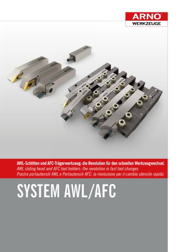 SYSTEM AFC & AWL
 SYSTEM SHARK-DRILL²
 SYSTEM Tool-Tip AS1005
 SYSTEM Tool-Tip AM7010-7020
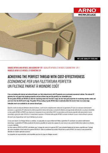 SYSTEM Tool-Tip AP3815/AP3925
 Catalogue drilling
 Catalogue milling
 Catalogue turning & threading
 Catalogue auto lathes