- Catalogs
- Arno Werkzeuge
- Catalogue auto lathes

Catalogue auto lathes

Catalogue auto lathes
- Tool Systems: ARNO offers a variety of tool systems designed for sliding headstock lathes, including the AFC system for quick tool changes and the AWL linear slide with integrated coolant supply.
- Innovative Highlights: The document emphasizes the efficiency of ARNO's tool systems in mass production of long, thin components, featuring precise and durable tools, effective cooling, and easy tool changes.
- Cooling Systems: The ACS (ARNO Cooling System) is patented for optimal cooling during parting, grooving, and turning operations, ensuring efficient chip evacuation and tool longevity.
- Tool Inserts: ARNO provides a wide range of positive and highly positive inserts for high-precision machining, suitable for challenging materials and small components.
- Modular Systems: The document lists various modular systems like DECO-CUT for grooving and threading, and SIM for internal machining, catering to different machining needs.
- Multifunctional Tools: SHARK-CUT is highlighted as a multifunctional tool for both turning and drilling operations.
- Personalized Assistance: ARNO assigns a personal contact to assist customers in optimizing their production processes, offering valuable advice through regular visits or phone consultations.
- Rapid Delivery: Orders placed by 6 PM (4 PM on Fridays) are delivered the next business day, ensuring quick access to tools, with special solutions also available swiftly.
- Expertise: ARNO leverages decades of experience and expertise to provide solutions for complex machining tasks, with a commitment to finding or developing the right solution for every challenge.
- Tool Life and Productivity: The ACS enhances tool life by 300% and triples productivity on average.
- Process Reliability: The system offers a cost-effective and optimized solution for reliable grooving processes.
- Cooling System: The ACS provides optimal cooling by directing coolant through the insert seat, improving chip removal and surface quality.
- Inserts: Available in 2-fluted sintered or ground forms, with special geometries for specific applications.
- Monoblock Holders: Shank sizes range from 8x8 mm to 20x20 mm, with groove widths from 1.5 mm to 3.0 mm.
- Design: The monoblock design is reliable and user-friendly, requiring only one spare part.
- The ACS system directs coolant along the insert seat, enhancing cooling efficiency and chip flushing.
- It reduces edge build-up and improves surface quality, allowing for higher cutting speeds and feed rates.
- The ACS2 variant cools the tool flank from underneath, further increasing tool life and process reliability.
- The system is suitable for auto lathes and sliding head machines, offering flexibility and ease of use.
- Technical suggestions and application references are provided to optimize performance in various machining scenarios.
1. Burr-Free Parting-Off: To achieve a burr-free surface finish, use ground inserts with minimal approach angles. A larger approach angle can reduce burr formation. Ensure short tool overhang and strong insert locking for stability and straightness.
2. Parting-Off Tube: Avoid excessive tool overhang to prevent instability and tool breakage. Select tools that are as short and narrow as possible. Higher approach angles reduce cutting forces.
3. Precision Grooving: This is the most economical and productive method for groove production. The ARNO grooving range offers various groove widths with a tolerance of +/- 0.02 mm.
1. System Overview: The SE groove turning system with ARNO Cooling System (ACS1) is designed for parting off, grooving, and copy turning. It supports radial parting off with widths of 2-3 mm and depths of 12-21 mm. The system ensures reliable clamping and precision repeatability.
2. Inserts and Holders: Available in six geometries and five styles, with specific designs for different materials. The system includes monoblock holders with shank sizes from 12x12 to 20x20 mm and groove widths from 2 to 3 mm.
3. Cooling System: The patented ACS1 cooling system directs coolant along the insert seat for optimal cooling, reducing edge build-up and improving surface quality.
1. Feed Rates and Groove Widths: Various feed rates and groove widths are recommended for different geometries and materials.
2. System Benefits: The SE grooving system offers stability, efficient cooling, and reliable processes for maximum productivity.
The document details various tool holders and boring bars used in internal machining, specifically for turning and threading applications. The tool holders have a helix angle of 1.5°, and support pads with different inclination angles are available separately. The document references Chapter 9 of the "Tools and indexable inserts for turning and threading" catalogue for additional support pads and matching indexable inserts.
Procedures:
Tool holders with screw clamping are used for internal machining. When extra accuracy is required, or when the bar length to diameter ratio exceeds 3:1, tool holders with a carbide shank are recommended. The overhang should be minimized to reduce vibrations, and the minimum length in the clamping device should be three times the diameter of the bar.
Standards and Recommendations:
For optimal performance, it is recommended to use tool holders with a solid carbide core to minimize vibrations. The document also suggests using mini holders on automatic lathes for precision industries, suitable for both external and internal threading.
Key Data from Tables:
The tables provide detailed specifications for various tool holders and boring bars, including dimensions, insert types, and spare parts. For example, the NVRC 10-2 tool holder has dimensions of 18 mm height, 180 mm length, and uses the 11I... insert.
Additional Information:
The document includes references to ISO indexable inserts, with sections on system presentation, ISO designation systems, grade descriptions, geometry descriptions, recommended cutting data, and application notes. These sections provide comprehensive guidance on selecting and using the appropriate inserts for specific machining tasks.
The document provides detailed descriptions of various indexable inserts, focusing on their geometries and applications. It covers a range of materials, including soft materials like aluminum and exotic materials such as titanium and super alloys. The inserts are available in different coated and uncoated grades, geometries, and sizes, with corner radii ranging from 0.05 to 3.0 mm.
ARNO offers a diverse range of high-positive indexable inserts known for their precision grinding and polished chip breakers. These inserts are designed for low cutting forces and high-quality surface finishes, making them ideal for long-chipping materials and thin-walled components.
The high-positive indexable inserts provide the largest diversity of geometries globally, ensuring extremely sharp and smooth cutting. They are suitable for both soft and exotic materials, offering excellent thermal resistance and notch wear resistance.
ARNO's inserts are suitable for a wide range of applications, from light machining to roughing, and are particularly effective for machining tough materials due to their high notch wear resistance and thermal resistance. The document highlights the importance of using the right coatings for optimal performance.
The document suggests specific cutting parameters for different materials and applications, emphasizing the importance of selecting the appropriate insert type and coating for the material being machined.
Examples are provided to illustrate the effectiveness of ARNO's indexable inserts in various machining scenarios, demonstrating their reliability and precision in producing high-quality results.
1. Cast Iron: Various types including ferritic, pearlitic, and high-strength austenitic with Brinell hardness ranging from 155 to 265 and tensile strength from 518 to 885 N/mm².
2. Aluminum Alloys: Includes non-hardenable and hardenable types with tensile strength up to 343 N/mm².
3. Copper Alloys: Includes electrolytic copper and short chip alloys with tensile strength up to 382 N/mm².
4. Refractory Alloys: Iron, nickel, and cobalt-based alloys with tensile strength up to 1177 N/mm².
5. Titanium Alloys: Pure and alloyed types with tensile strength up to 1396 N/mm².
6. Non-Metallic Materials: Includes thermoplastics and reinforced plastics with specific cutting parameters.
1. Suggested Cutting Speeds: Vary based on material type and hardness, with specific recommendations for carbide tools with and without coating.
2. Tool Specifications: Includes corner radius and clearance angles for inserts, with a standard clearance angle of 7° for primary cutting and 3° for secondary cutting.
1. Multi-Purpose Tool: Designed for turning and drilling operations, reducing tool changes and programming time.
2. Variants: SHARK-CUT Mini for diameters 4 to 8 mm and SHARK-CUT Standard for diameters 8 to 32 mm.
3. Benefits: Economical, fast, and high-quality surface finish with fewer tool positions required.
1. Nickel or Cobalt-based alloys are categorized into annealed, hardened, and cast forms with varying tensile strengths and temperatures.
2. Titanium alloys include pure titanium and Alpha + Beta, and Beta alloys, each with specific tensile strengths and temperature ratings.
3. Tungsten and molybdenum alloys have similar properties, with a focus on high modulus of elasticity and density.
4. Hardened steels and cast irons are specified by their hardness ratings (HRC).
1. SHARK-CUT® tools are recommended for various machining operations such as boring, facing, and drilling.
2. Cutting depths and feed rates are specified for different tool diameters, with variations for coated and uncoated carbides.
3. Recommended coolant pressures are provided to optimize chip evacuation and tool performance.
1. SHARK-CUT® tools are designed for off-centre drilling, allowing for deviations in tool diameter.
2. The WIPER geometry of inserts improves surface quality and reduces machining time by allowing higher feed rates.
3. Specific guidelines are provided for through-hole drilling and machining over the center, emphasizing the importance of correct tool positioning and coolant pressure.
1. Application references and technical suggestions are provided for optimizing tool performance and ensuring safety during operations.
2. The document emphasizes the importance of adjusting machine settings to accommodate tool and workpiece specifications.
This document provides a comprehensive comparison of various materials, focusing on tool steels, stainless and heat-resistant steels, and grey cast iron. It includes detailed specifications for each material type, including their chemical compositions and corresponding international standards.
Tool Steels:
Tool steels are categorized by their chemical composition and mechanical properties. The document lists various grades such as 1.2344 (X 40 CrMoV 5 1), 1.2363 (X 100 CrMoV 5 1), and others, along with their equivalent standards in different countries like Germany (DIN), UK (BS), and USA (AISI/SAE/ASTM).
Stainless and Heat-Resistant Steels:
This section covers stainless steels like 1.4301 (X 5 CrNi 18 10) and heat-resistant alloys such as 1.4845 (X12CrNi25-21). Each entry includes equivalent grades across various international standards, highlighting their applications in environments requiring corrosion resistance and high-temperature stability.
Grey Cast Iron:
The document details grey cast iron grades such as EN-JL1010 (GG-10) and EN-JL1060 (GG-35), providing their mechanical properties and equivalent standards in different countries.
Material Comparison Tables:
Tables are provided to compare materials across different international standards, including ISO, DIN, BS, AFNOR, UNI, SS, UNE, JIS, and GOST. These tables facilitate the selection of materials based on regional availability and compliance with local standards.
Key Takeaways:
- The document serves as a reference for selecting materials based on their mechanical properties and international equivalencies.
- It emphasizes the importance of understanding material standards across different countries for global manufacturing and engineering applications.
- The tables and specifications are crucial for engineers and manufacturers in ensuring material compatibility and performance in various industrial applications.
The document provides detailed specifications and procedures for machining operations, focusing on cutting parameters and tool selection. Key parameters include cutting speed, feed rate, and cutting depth, which are crucial for optimizing machining performance and reducing tool wear.
- Microsoldering: Occurs due to low cutting temperatures and inadequate chip evacuation. Solutions include increasing cutting speed and angle, selecting appropriate material grades, and ensuring proper coolant flow.
- Necking at Maximum Cutting Depth: Caused by oxidation and high temperatures at the cutting edge. Solutions involve varying cutting depths, reducing cutting speed, and checking coolant efficiency.
- Cracks Perpendicular to Cutting Edge: Result from thermal fluctuations and coolant blockages. Solutions include reducing cutting speed, using special grades, and maintaining continuous coolant supply.
The document includes formulas for calculating chip cross-section, cutting force, chip thickness, and specific cutting force. It also provides guidelines for calculating drive power, operating time, and machined turning length.
Vibrations are common in machining long, thin workpieces or using long boring bars. Recommendations to reduce vibrations include using short clamping tools, selecting appropriate cutting depths, and adjusting cutting speeds.
Guidelines for selecting tools and inserts to minimize vibrations and optimize machining performance. Emphasis is placed on the importance of tool clamping, cutting depth, and speed adjustments.
ARNO®-Werkzeuge offers a wide range of tool systems for various metal-working applications, emphasizing their experience, quality, and innovative solutions to enhance production efficiency.
Catalog excerpts

Tools and inserts for sliding head auto lathes Utensili ed inserti per macchine a fantina mobile Outils et plaquettes pour le décolletage SLIDING HEAD AUTO LATHES
Open the catalog to page 1
Contents / Indice / Contenu Page / Pagina / Page • ATS system - AFC too holders and cutting inserts • Sistema ATS - Attrezzi di supporto AFC e inserti • Système ATS - Porte-outils AFC et inserts de coupe • System SA and SE - AFC tool holders • Sistema SA e SE - Attrezzi di supporto AFC • AFC Holders with lever lock clamping • Steli AFC con bloccaggio a leva • Supports de serrage AFC avec serrage par levier • AFC Holders with srew clamping • Steli AFC con bloccaggio a vite • Supports de serrage AFC avec serrage par vis • AFC Holders for thread turning • Supports de serrage AFC á filetage • System...
Open the catalog to page 2
Contents / Indice / Contenu • System presentation • Tool holders ˗ Tool holders • Inserts ˗ Parametri di taglio suggeriti ˗ Description of grades ˗ Recommended cutting data ˗ Paramètres de coupe suggérés • Application notes • Suggerimenti tecnici • Données d’application • ISO-Designation System • System presentation • Tool shank options • Tipologie di corpo utensile • ISO toolholder for external machining Shank 8×8 mm – 20×20 mm • Steli ISO per tornitura esterna Stelo 8×8 mm – 20×20 mm • Porte-outil ISO pour usinage extérieur Tige 8×8 mm – 20×20 mm • ISO tool holder for internal machining Shank...
Open the catalog to page 3
ARNO solutions for Swiss type machining IF YOU HAVE A SWISS TYPE MACHINE, YOU SHOULD GET TO KNOW ARNO. With ARNO you benefit from reliable processes, long tool life, a revolutionary tool changing system and more productivity in your Swiss type machining production shop. How do you make working with Swiss type machines more efficient? By using the well thought-out tool systems from ARNO! You benefit from long tool life, reliable processes, optimised cooling and simple, fast tool changes. Find out here how ARNO systems for Swiss type turning result in more productivity in your production. If you...
Open the catalog to page 4
ARNO solutions for Swiss type machining 0 1 2 3 4 5 6 7 8 9 i ARNO®-Werkzeuge | Auto lathes | Fantina mobile | Décolletage
Open the catalog to page 5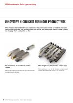
ARNO solutions for Swiss type machining INNOVATIVE HIGHLIGHTS FOR MORE PRODUCTIVITY. When the application involves the mass production of long narrow parts made of bar material, Swiss type machines are unbeatable. They work even better with precise, long-lasting tools, effective cooling and easy tool changing. That’s exactly what we offer: AFC tool holders: the revolution in fast tool changes Perfect for simple, reliable and fast tool changes: the two-part AFC holder makes tool changes so easy and lightning fast. ARNO®-Werkzeuge | Auto lathes | Fantina mobile | Décolletage AWL siding heads: with...
Open the catalog to page 6
ARNO solutions for Swiss type machining Your Swiss type machining specialists: indexable inserts with PS geometries and high-positive indexable inserts for high surface quality. Perfect for high-precision machining with demanding materials and thin-walled components: ARNO offers the largest standard portfolio of high-positive indexable inserts in the world, including intermediate sizes and edge-honed executions. So there is a best possible solution for every complex challenge. The ACS – ARNO Cooling System: the patented cooling system for efficient parting off, grooving and groove turning with...
Open the catalog to page 7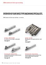
ARNO solutions for Swiss type machining OVERVIEW OF OUR SWISS TYPE MACHINING SPECIALISTS. ARNO systems for Swiss type machining – an overview. AFC Holders | ARNO FAST CHANGE The revolution in fast tool changes – patent applied. Toolholder – Auto lathes AWL sliding head: with integrated coolant feed – patent applied. SA-Grooving system | External machining Extremely efficient and flexible for parting off and grooving diameters up to Ø 44 mm. SE-Grooving system | External machining Extremely versatile for parting off, grooving and copy turning: the ARNO SE groove turning system. ARNO®-Werkzeuge...
Open the catalog to page 8
ARNO solutions for Swiss type machining AMS – ARNO Mini-System | Internal machining system For internal machining starts at a diameter of 0.7 mm and reaches drilling depths of up to 50 mm. SIM – Boring bars | Internal machining The optimal solution for internal machining from bore diameters of 6.7 mm: the modular ARNO SIM System. Turning | ISO toolholder Wide range of ISO turning holders and indexable inserts for Swiss type machining DECO-CUT | Groove turning system Parting off, grooving, groove turning, threading: the modular DECO-CUT system from ARNO. SHARK-CUT® | Multi purpose tool Turning...
Open the catalog to page 9
ARNO Services OUTSTANDING WHEN IT COMES TO SERVICE. We do our utmost for you to achieve success: from comprehensive consulting by our machining experts and fast implementation of special solutions through to overnight delivery. As a family-owned company, we focus on successful long-term business relations with our customers. That’s why we prefer to develop well-designed products than start short-term sales promotions. And if you use these products in your production, we make sure that there is a benefit for you: efficient, reliable and simple production processes. At ARNO you are assigned a personal...
Open the catalog to page 10
ARNO Services We are close to you all over the world Our tools are in use all over the world – that’s why we are close to you all over the world. You can reach us easily through our subsidiaries and distributors. Karl-Heinz Arnold GmbH Karlsbader Str. 4 | D-73760 Ostfildern Tel +49 (0)711 34 802 0 Fax +49 (0)711 34 802 130 [email protected] | www.arno.de ARNO Italia S.r.l. Via J. F. Kennedy 19 | 20871 Vimercate (MB) Tel +39 039 68 52 101 [email protected] | www.arno-italia.it ARNO (UK) Limited Unit 9, 10 & 11, Sugnall Business Centre Sugnall, Eccleshall Staffordshire | ST21 6NF Tel +44 01785...
Open the catalog to page 11All Arno Werkzeuge catalogs and technical brochures
 COMPETENCE turning
52 Pages
 COMPETENCE swiss type machining
44 Pages
 COMPETENCE parting and grooving
44 Pages
 SYSTEM ATS
36 Pages
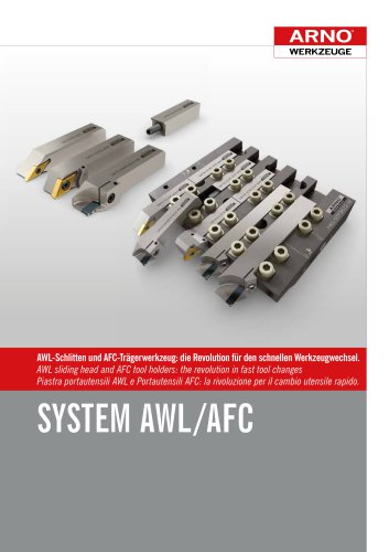 SYSTEM AFC & AWL
108 Pages
 SYSTEM SHARK-DRILL²
40 Pages
 SYSTEM Tool-Tip AS1005
4 Pages
 SYSTEM Tool-Tip AM7010-7020
12 Pages
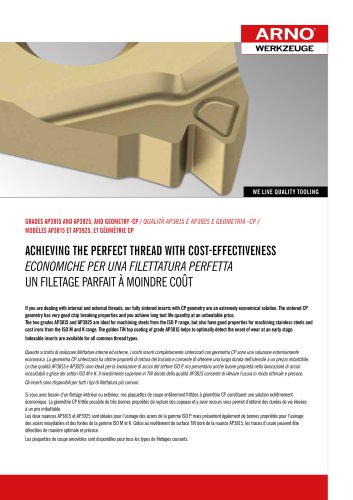 SYSTEM Tool-Tip AP3815/AP3925
24 Pages
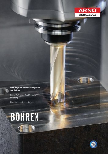 Catalogue drilling
284 Pages
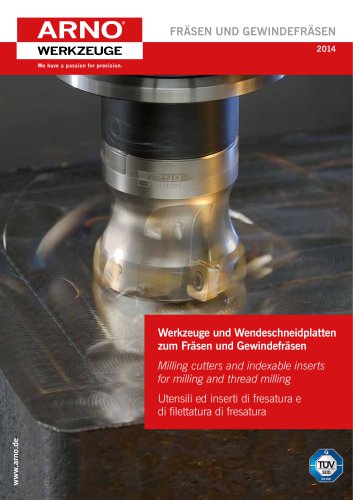 Catalogue milling
324 Pages
 Catalogue turning & threading
804 Pages
 Catalogue parting and grooving
788 Pages