Catalog excerpts
Water hammer in valves solutions to improve stability 1. Causes of water hammer 2.1. 2.2. Hydraulic water hammer and cavitational hammer Thermal water hammer Measures to prevent water hammer Influence of water hammer on valves Body strength Body seals Stem seals Design and choice of material Choice of seals and chambers Bellows design Fraunhofer UMSICHT - Institute Tests on the FABA®-Plus-Valve Tests on the FABA®-Supra-Valve Dipl.-Ing. Erhard Stork, ARI-Armaturen Albert Richter GmbH & Co. KG, D-33756 Schloß Holte-Stukenbrock Tel.: +49 5207/994-0, Fax: +49 5207/994-297, E-Mail: info.vertrieb@ari-armaturen.com, Internet:: http://www.ari-armaturen.com t000026150-2.doc
Open the catalog to page 1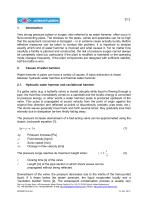
Very strong pressure pulses or surges, also referred to as water hammer, often occur in fluid-conducting pipes. The stresses on the pipes, valves and apparatus can be so high that the equipment concerned is damaged – or in extreme cases actually bursts. Before effective measures can be taken to combat this problem, it is important to analyse exactly which kind of water hammer is involved and what causes it. Yet no matter how carefully a facility is planned and constructed, the risk of pressure surges cannot always be completely ruled out, particularly if the plant is modified or extended or...
Open the catalog to page 2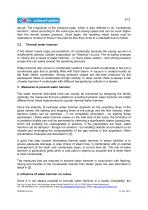
3/12 abrupt. The magnitude of the pressure peak, which is also referred to as "cavitational hammer", varies according to the valve type and closing speed and can be much higher than the normal system pressure. Once again, the resulting shock waves may be replicated a number of times in the pipe be-fore they come to a standstill due to friction. 2.2. Thermal water hammer If hot steam meets large accumulations of condensate because the piping sys-tem is insufficiently drained, sudden evaporation (or "flashing") occurs. The re-sulting changes in volume are a cause of water hammer – in many...
Open the catalog to page 3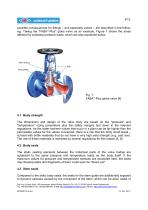
4/12 possible consequences for fittings – and especially valves – are described in the following. Taking the "FABA®-Plus" globe valve as an example, Figure 1 shows the areas affected by pulsating pressure loads, which are also explained below. Fig. 1: FABA®-Plus globe valve [4] 4.1. Body strength The dimensions and design of the valve body are based on the "pressure" and "temperature" sizing parameters plus the safety margins laid down in the relevant regulations. As the water hammer values that occur in a plant can be far higher than the permissible values for the valves concerned, there...
Open the catalog to page 4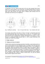
5/12 a combination of the two. Manual valves tend to be only rarely operated while control valves are in action regularly, if not continuously. The gland packing (Figure 2) and the PTFE V-ring unit (Figure 3) are the two classic systems. If this kind of seal is already badly worn, water hammer can easily result in leakage; gland packings have the advantage here that they can be retightened. Fig. 3: V-ring unit stem seal Fig. 4: Bellows stem seal The stainless steel bellows seal shown in Figure 4 provides a permanently leak-proof and maintenance-free stem seal because wear is ruled out. The...
Open the catalog to page 5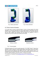
5.2. Choice of seals and chambers It is a good idea to choose a grooved design in order to prevent gaskets from being damaged, or in the worst case blown out, due to water hammer. These seals, which are shown in Figure 7, generally consist of a shaped metal carrier and a soft seal. Once the seal has been installed and preloaded, the soft material, e.g. graphite or PTFE, is pressed into the carrier profile to give additional anchorage. Delivery condition Assembly condition Fig. 7: Grooved gasket Chambered gaskets are another possible alternative. The "FABA®-Supra C" globe valve depicted in...
Open the catalog to page 6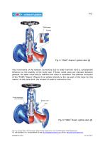
Weld seam Gasket Fig. 8: FABA®-Supra C globe valve [4] The movements of the bellows connectors due to water hammer have a considerable influence on the stability of the body seal. If these metal parts are clamped between gaskets, the latter could fail if a defined limit value is exceeded. The bellows connector of the "FABA®-Supra" (Figure 8) is welded directly to the top part of the body for this reason. At the same time, the number of seals is reduced to one. Fig. 9: FABA®-Supra i globe valve [4] Dipl.-Ing. Erhard Stork, ARI-Armaturen Albert Richter GmbH & Co. KG, D-33756 Schloß...
Open the catalog to page 7
8/12 5.3. Bellows design To prevent water hammer from damaging metal bellows, the bellows must be designed with sufficient compressive strength, including appropriate reserves. As a way to increase the nominal pressure, multi-walled designs should be preferred to single-walled bellows with thicker walls. The wall in contact with the fluid performs the sealing function while the other walls serve to support the bellows and give them a higher compressive strength. Since increasing the wall thickness or the number of walls simultaneously makes the bellows more rigid (higher spring rate), these...
Open the catalog to page 8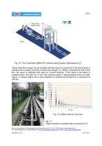
Fast acting butterfly valve Fig. 10: The Fraunhofer UMSICHT Institute testing facility (Oberhausen) [7] These maximum values can be doubled with the help of a small trick if the shock wave is directed into a branch line with a closed end (Figure 11). When it reaches the end of this line, the wave is reflected with twice its normal intensity. If the valve to be tested is installed there, the load on it from the pressure peak is approximately twice as high. Figure 12 shows clearly how it was possible to increase the pressure to a maximum of 200 bar. Fig. 12: Water hammer over time Fig. 11:...
Open the catalog to page 9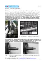
10/12 6.2 Tests on the FABA®-Plus-Valve The first tests were conducted on a standard "FABA®-Plus" valve (DN 80 / PN 40) as shown in Figure 1. In Figure 13, the valve is installed at the end of the pipe. The video provides a good visual and acoustic impression of the high loads. By successively increasing the water hammer, the Institute was able to determine the limit above which this standard 2-walled bellows is deformed. This valve is designed for a maximum pressure of 40 bar, yet there were still no negative values at 100 bar and no change to the bellows or the bonnet seal (Figure 14)....
Open the catalog to page 10All ARI-Armaturen catalogs and technical brochures
-
 CONA® Compact discharge
7 Pages
-
 STEVI-POS
2 Pages
-
 ZEDOX HEXO
5 Pages
-
 ARI-STEVI Smart 425/426
16 Pages
-
 ARI-STEVI Pro 470/471 ANSI
28 Pages
-
 FABA - Bellows sealed valve
5 Pages
-
 SAFE - Variable & safe
8 Pages
-
 CONA All-in-One
2 Pages
-
 PREMIO Plus 2G
2 Pages
-
 STOBU
STOBU2 Pages
-
 FABA
FABA5 Pages
-
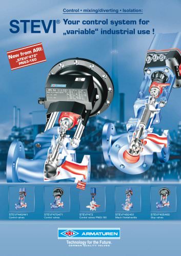
 STEVI - Control valves
9 Pages
-
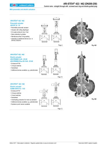 ARI-STEVI Pro 422/462
20 Pages
-
 ARI-STEVI Pro 470/471
28 Pages
-
 SAFE Flyer
2 Pages
-
 CONA - Compact discharge
7 Pages
-
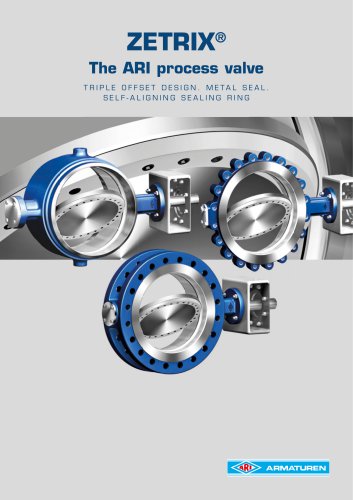
 ZETRIX - ARI process valve
8 Pages
-
 CONLIFT
2 Pages
-
 FABA - the new generation
5 Pages
-
 ARI systems
2 Pages
-
 SHR
SHR2 Pages
-
 PREMIO ® -Plus 2G
2 Pages
-
 CONA®B
2 Pages
-
 mechanical condensate pump
2 Pages
-
 Back pressure safety valves
12 Pages
-
 ARI SAFE SN ANSI
16 Pages
-
 ARI SAFE
36 Pages
-
 ARI tempotal
20 Pages
-
 ARI PRESO
4 Pages
-
 472 series
24 Pages
-
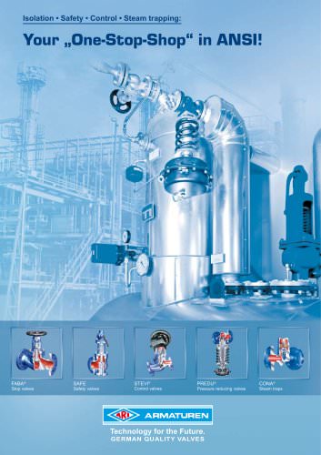 Your "One-Stop-Shop" in ANSI
8 Pages
-
 e.g. ARImetec-DX
4 Pages


Archived catalogs
-
 e.g. SAFE / SAFE-P
2 Pages
-
 Application engineering
2 Pages
-
 EURO-WEDI
2 Pages
-
 PREMIO Plus
2 Pages
-
 TEMPTROL
2 Pages
-
 STEVI AS
6 Pages
-
 ARI-CODI S
8 Pages
-
 ARI-CONA B
20 Pages
-
 ARI-Strainer
6 Pages
-
 ARI-FABA Long Life
16 Pages
-
 ARI-Check valve
12 Pages
-
 Pressure Reducing Valve
6 Pages
-
 Metallic sealing
4 Pages