Catalog excerpts

Capacity chart The capacity chart shows the maximum flow at factory setting. (Other factorysettings for the sub-cooling on request.) Curve 1: Maximum flow quantity of hot condensate at approx. 10 K below boiling temperature. Curve 2: Maximum flow of sub-cooled condensate at approx. 30 K below boiling temperature (through back up of condensate). Curve 3: Maximum flow quantity of cold condensate at about 20°C (during start-up of a cold installation). Parts Pos. Description Fig. 12.600 1 Body EN-GJL-250, EN-JL1040 2 Strainer * X5CrNi18-10, 1.4301 6 Cover EN-GJL-250, EN-JL1040 11 Sealing ring *...
Open the catalog to page 3
Capacity chart The capacity chart shows the maximum flow at factory setting. (Other factory-settings for the sub-cooling on request.) Curve 1: Maximum flow quantity of hot condensate at approx. 10 K below boiling temperature. Curve 2: Maximum flow of sub-cooled condensate at approx. 30 K below boiling temperature (through back up of condensate). Curve 3: Maximum flow quantity of cold condensate at about 20°C (during start-up of a cold installation). The condensate temperature determines the opening of the controller. Capacity is increased with the sub-cooling temperature of the condensate....
Open the catalog to page 5
CONA®B 600 / 601 PN40 - DN40-50 Options Outside strainer with blow down valve Ball valve with adapter for blow down with internal strainer (restricted to 16 bar, 210°C) Parts Pos. Description Fig. 45.600 / 45.601 Fig. 85.600 / 85.601 Fig. 55.600 / 55.601 1 Body P250 GH, 1.0460 16Mo3, 1.5415 X6CrNiTi18-10, 1.4541 2 Strainer * X5CrNi18-10, 1.4301 6 Deckel P250 GH, 1.0460 16Mo3, 1.5415 X6CrNiTi18-10, 1.4541 7 Strainer screen * X5CrNi18-10, 1.4301 8 Strainer plug * X6CrNiTi18-10, 1.4541 24 Controller * TB 102 / 85 (corrosion resistant bimetal) 26 Sealing ring * Graphite (CrNi laminated with...
Open the catalog to page 7
Capacity chart The capacity chart shows the maximum flow of hot and cold condensat at factory setting. For operating pressures below 5 bar, a correction of the factory-setting acc. to manufacturers information is recommended.) Curve 1: Maximum flow quantity of hot condensate at approx. 15 K below boiling temperature. Curve 2: Maximum flow of sub-cooled condensate at approx. 30 K below boiling temperature (through back up of condensate). Curve 3: Maximum flow quantity of cold condensate at about 20°C (during start-up of a cold installation). The condensate temperature determines the opening...
Open the catalog to page 9
ss 11 Parts Pos. Description Fig. 86.600 / 87.600 1 Body 16Mo3, 1.5415 2 Strainer * X5CrNi18-10, 1.4301 6 Cover 16Mo3, 1.5415 24 Controller * TB 102 / 85 (corrosion resistant bimetal) 26 Sealing ring * Graphite (CrNi laminated with graphite) 28 Hexagonal nut 21CrMoV 5-7, 1.7709 29 Erosion deflector * X17CrNi16-2, 1.4057 30 Extension sleeve 21CrMoV 5-7, 1.7709 36 Stud 21CrMoV 5-7, 1.7709 * Spare part Information / restriction of technical rules need to be observed! Operating instructions can be ordered by phone +49 (0)5207 / 994-0 or fax +49 (0)5207 / 994-158 or -159. CONA®B 600 PN63 / PN100...
Open the catalog to page 11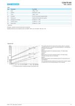
13 Capacity chart The capacity chart shows the maximum flow at factory setting. For operating pressures below 5 bar, a correction of the factory-setting acc. to manufacturers information is recommended.) Curve 1: Maximum flow quantity of hot condensate at approx. 15 K below boiling temperature. Curve 2: Maximum flow of sub-cooled condensate at approx. 30 K below boiling temperature (through back up of condensate). Curve 3: Maximum flow quantity of cold condensate at about 20°C (during start-up of a cold installation). The condensate temperature determines the opening of the controller....
Open the catalog to page 13
15 Capacity chart PN160 The capacity chart shows the maximum flow at factory setting. For operating pressures below 15 bar, a correction of the factory-setting acc. to manufacturers information is recommended.) Curve 1: Maximum flow quantity of hot condensate at approx. 10 K below boiling temperature. Curve 2: Maximum flow of sub-cooled condensate at approx. 30 K below boiling temperature (through back up of condensate). Curve 3: Maximum flow quantity of cold condensate at about 20°C (during start-up of a cold installation). The condensate temperature determines the opening of the...
Open the catalog to page 15
17 Capacity chart The capacity chart shows the maximum flow at factory setting. For operating pressures below 15 bar, a correction of the factory-setting acc. to manufacturers information is recommended.) Curve 1: Maximum flow quantity of hot condensate at approx. 10 K below boiling temperature. Curve 2: Maximum flow of sub-cooled condensate at approx. 30 K below boiling temperature (through back up of condensate). Curve 3: Maximum flow quantity of cold condensate at about 20°C (during start-up of a cold installation). The condensate temperature determines the opening of the controller....
Open the catalog to page 17
18 Informations about pipe welding Welding groove acc. to DIN 2559 The material used for ARI valves with butt weld ends are: 1.0619+N GP240GH+N acc. to DIN EN 10213-2 1.0460 P250GH acc. to DIN EN 10222-2 1.0401 C15 acc. to DIN 17210 1.5415 16Mo3 acc. to DIN EN 10028 1.4541 X6CrNiTi18-10 acc. to DIN EN 10088 1.7335 13CrMo4-5 acc. to DIN EN 10028 1.7380 10CrMo 9-10 acc. to DIN EN 10028 1.4903 X10CrMoVNb 91 acc. to VdTÜV Data sheet 511/3 (06.99) 1.4905 X11CrMo WVNb 9-1-1 acc. to VdTÜV Data sheet 522/3 (06.99) 1.4901 X10CrWMoVNb9-2, 1.4901 acc. to VdTÜV Data sheet 552/3 (12.2007) Due to our...
Open the catalog to page 18
20 ARI-Armaturen Albert Richter GmbH & Co. KG, D-33756 Schloß Holte-Stukenbrock, Tel. +49 52 07 / 994-0, Telefax +49 52 07 / 994-158 or 159 Internet: http://www.ari-armaturen.com E-mail: info.vertrieb@ari-armaturen.com Multifunction tester ARImetec®-S Condensate collection (B = 160), steam distribution (B = 120) CODI ®S with gland packing Fig. 671/672; Vacuum breaker Fig. 655 CODI ®B with bellows seal, maintenance-free Fig. 675/676 Automatic air vent for liquid systems Fig. 656 Condensate discharge temperature limiter Fig. 645/647 Flow indicator Fig. 660/661 Return temperature limiter Fig....
Open the catalog to page 20All ARI-Armaturen catalogs and technical brochures
-
 CONA® Compact discharge
7 Pages
-
 STEVI-POS
2 Pages
-
 ZEDOX HEXO
5 Pages
-
 ARI-STEVI Smart 425/426
16 Pages
-
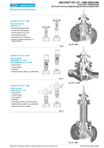 ARI-STEVI Pro 470/471 ANSI
28 Pages
-
 FABA - Bellows sealed valve
5 Pages
-
 SAFE - Variable & safe
8 Pages
-
 CONA All-in-One
2 Pages
-
 PREMIO Plus 2G
2 Pages
-
 STOBU
STOBU2 Pages
-
 FABA
FABA5 Pages
-
 STEVI - Control valves
9 Pages
-
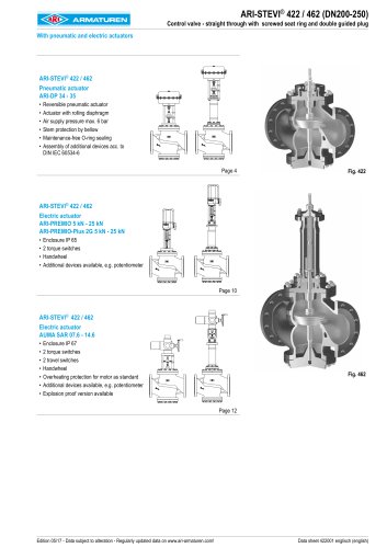 ARI-STEVI Pro 422/462
20 Pages
-
 ARI-STEVI Pro 470/471
28 Pages
-
 SAFE Flyer
2 Pages
-
 CONA - Compact discharge
7 Pages
-
 ZETRIX - ARI process valve
8 Pages
-
 CONLIFT
2 Pages
-
 FABA - the new generation
5 Pages
-
 ARI systems
2 Pages
-
 SHR
SHR2 Pages
-
 PREMIO ® -Plus 2G
2 Pages
-
 CONA®B
2 Pages
-
 mechanical condensate pump
2 Pages
-
 Back pressure safety valves
12 Pages
-
 ARI SAFE SN ANSI
16 Pages
-
 ARI SAFE
36 Pages
-
 ARI tempotal
20 Pages
-
 ARI PRESO
4 Pages
-
 472 series
24 Pages
-
 Your "One-Stop-Shop" in ANSI
8 Pages
-
 e.g. ARImetec-DX
4 Pages


Archived catalogs
-
 e.g. SAFE / SAFE-P
2 Pages
-
 Application engineering
2 Pages
-
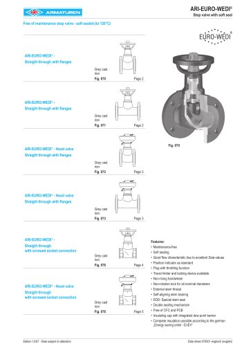
 EURO-WEDI
2 Pages
-
 PREMIO Plus
2 Pages
-
 TEMPTROL
2 Pages
-
 STEVI AS
6 Pages
-
 ARI-CODI S
8 Pages
-
 ARI-Strainer
6 Pages
-
 ARI-FABA Long Life
16 Pages
-
 ARI-Check valve
12 Pages
-
 Pressure Reducing Valve
6 Pages
-
 Metallic sealing
4 Pages