
- Catalogs
- ARGO-HYTOS
- PRM7-06


PRM7-06

PRM7-06
- M16x1.5 Connector: Available without rectifier, suitable for bushing bore diameter of 4-6 mm, with ordering numbers 16202600 and 16202500 for 230 V DC.
- M23 Connector: 7PIN female connector with ordering number 345579500001.
- M12x1 Connector: 5PIN male connector, specific to E03 and E04S01 configurations, with ordering number 358359000002.
- G4W1F Connector: Ordering number 358358932157.
- M12x1 Connector Cover: Ordering number 23090600.
- Standard NBR70: Includes square rings (9.25 x 1.68 mm, 4 pcs.) and O-rings (17 x 1.8 mm, 2 pcs.), ordering number 15845200.
- Viton: Includes square rings (9.25 x 1.78 mm, 4 pcs.) and O-rings (17.17 x 1.78 mm, 2 pcs.), ordering number 15845400.
- Standard NBR70: Size 32 x 2 mm, 1 piece, ordering number 273111014140.
- Specifications: M5 x 45 DIN 912-10.9, 4 pieces, with a tightening torque of 8.9 Nm (6.6 ft-lbs), ordering number 15845100.
Catalog excerpts
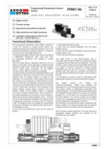
Proportional Directional Control Valves Compact design Operated by proportional solenoids High sensitivity and slight hysteresis Digital control Installation dimensions to DIN 24 340 / ISO 4401 / CETOP RP121-H Functional Description The proportional directional valve PRM7 consists of a cast iron housing, a special control spool, two centering springs with supporting washers, one or two proportional solenoids, a position sensor or, if need be, of a control box with digital electronics. The measuring system of the position sensor consists of a differential transformer with core and from the evaluating electronic unit realized in hybrid technique. With the model without integrated electronic unit, the electric connection of the solenoids is realized by the connector plug to EN 175301-803, with the position sensor output being connected by the G4W1F connector plug. Both connectors are supplied. The proportional valve with the integrated electronic unit comprises an electronic control box that is mounted, together with the position sensor, on either of the solenoids. The connection of the position sensor with the control box is provided by a cable. With the model with two solenoids, the solenoid mounted opposite the control box is connected with the control box by means of a EN 175301-803, connector. The connection of the supply voltage, control signal, program input and external output of the position sensor is realized by a 5-pin connector (ELKA 5012). The connection of the external feedback is provided by a 5-pin connector, which also has three supply voltages +24 V, +10V and -5V for an external sensor available. The solenoid coils, including the control box, can be turned in a range of ± 90o.The digital control unit enables the proportional valve to be controlled on the basis of data required from two feedback circuits. In this case the proportional valve can be used as follows: 1. Proportional directional valve 2. Only with the internal feedback from the spool position sensor. 3. Only with the external feedback (pressure sensor, position sensor, etc.). 4. With internal and external feedback. The outlet current to the electromagnet coils is controlled with the help of PWM. The electronic system is equipped with an internal current feedback. The outlet current in case of need may be modulated with the use of a signal of dynamic lubrication. Single function parameters are set up with the use of appropriate software with the help of a computer connected to the proportional switchboard through a serial interface RS 232. It is necessary to order a cable in accordance with appropriate ordering number as mentioned on page 4. The digital control unit utilizes the pulse-with-modulation (PWM) and supplies the solenoids with current proportional to the control signal. The supply current is additionally modulated with a dither frequency. The individual functional parameters are adjusted through software by means of a special programmer, or by means of a computer through the RS 232 interface. The correct function of the digital control unit is signaled by a green LED. The incorrect function (failure) is indicated by a red LED. As a standard, the proportional valve is delivered with factory setting. The model including also an external feedback shall be consulted with the manufacturer. With the basic surface treatment, the valve housing is phosphate coated, whereas the surfaces of the solenoids are zinc coated.
Open the catalog to page 1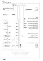
Ordering Code Proportional directional control Nominal size Spool Symbols without designation S01 position sensor with voltage outlet S02 position sensor with current outlet E01 proportional directional valve without proportional directional valve with position feedback proportional directional valve with external feedback proportional directional valve with position and external feedback Nominal solenoid supply voltage ** Cannot be supplied as Variant S2 Nominal flow rate at Ap = 10 bar Model for cylinders with asymmetric piston rod, piston area ratio 1:2 Connectors are to be ordered separately,...
Open the catalog to page 2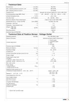
Technical Data Nominal size Max. operating pressure at ports P, A, B Max. operating pressure at port T Hydraulic fluid Hydraulic oils of power classes (HL, HLP) to DIN 51524 Fluid temperature range (NBR / Viton) Viscosity range Maximum degree of fluid contamination Nominal flow at Dp = 10 bar (145 PSI) Hysteresis - open loop Hysteresis - closed position loop Mounting position Technical Data of Position Sensor - Voltage Outlet Operating pressure Electric connection electrical connector G4W1F Hirschmann * Contact assignment 1 - Power supply 2 - Command signal 3 - GND 4 - not used Enclosure type...
Open the catalog to page 3
Technical Data of Position Sensor - Current Outlet Linearity Operating pressure Electrical connection electrical connector G4W1F Hirschmann * 1 - Power supply 2 - Command signal 3 - GND 4 - not used Contact assigment Operatin voltage Output signal range Output signal range used: 0 position 1 solenoid - stroke 2.8 mm (0.11 in) 2 solenoids - stroke ± 2.8 mm (0.11 in) Additional output signal error: - at temperature change from +10 ... 55 °C (50 ...131 °F) - at imjpedance change from 50% - at input voltage change in the range of operating voltage Limit frequency at 3 dB amplitude decrease Output...
Open the catalog to page 4
Limit Power Nominal flow 8 L/min (2.11 GPM) Nominal flow 5 L/min (1.32 GPM) Flow Characteristics Nominal flow 30 L/min (7.93 GPM) (18.5) Nominal flow 15 L/min (3.96 GPM) (13.2) Measured at input pressure D p =10 bar (145 PSI) , n = 32 mm /s (156 SUS) Command value [%]
Open the catalog to page 5
Flow Characteristics Measured at n = 32 mm /s (156 SUS) Dp=Valve pressure differential (inlet pressure pV minus load pressure and return pressure pT) Dpn = Valve pressure differential for nominal flow Qn
Open the catalog to page 6
closed position loop, for E02S01 model Frequency Reponse Connector Connection Connector K1- type M23 (male) PIN Technical data * Power supply input 1 * Ground (power supply) 2 Control signal 3 Ground (signal) 4 Power reference signal 5 Control signal of position sensor spool 6 * Protection earth lead (PE) 7 * Recommended min. lead cross section 0.75mm Connector K2 - type M12x1 (male) PIN Technical data Description TxD standard 1 RxD RS 232 2 Ground (signal) 0V 3 Not used 4 Connector K3 - type M12x1 (female) PIN Technical data Power supply output 1 Signal of external feedback 2 Ground 3 Not used...
Open the catalog to page 7All ARGO-HYTOS catalogs and technical brochures
 MLS3-06
10 Pages
 C5.3511 · C5.3516 · C5.3529
3 Pages
 LS 040 · LS 075
6 Pages
 ES 075
6 Pages
 Catalogue Hydraulic Drives
65 Pages
 Catalogue Filtration
342 Pages
 Catalogue Fluid Management
69 Pages
 Catalogue Lightline
50 Pages
 Filtration Guideline
20 Pages
 Off-line Filtration
2 Pages
 Light Line
4 Pages
 RC series
4 Pages
 TS3 MTS2
6 Pages
 ECOLINE
8 Pages


Archived catalogs
 TS4 MTS
6 Pages
 SR4P2-B2
4 Pages
 SR1P2-A2
4 Pages
 PRM7-10
10 Pages
 PRM8-06
4 Pages
 PRM2-04
20 Pages
 PRM6-10
20 Pages
 PRM2-06
20 Pages
 PRM7-04
10 Pages
 Coils
Coils18 Pages
 Datasheet RPEL1-06
6 Pages
 Datasheet RPH2-06
4 Pages
 Datasheet RPR3-04
4 Pages
 Solutions for clean Oil
6 Pages
 EXAPOR MAX 2
3 Pages
 Guidelines
21 Pages
 Brochure Wind Energy
2 Pages
 Agritechnica Highlights 2015
32 Pages
 MDA Highlights 2015
24 Pages
 Product summary
16 Pages
 Brochure for Endusers
2 Pages
 ARGO-HYTOS program summary
16 Pages


