
- Catalogs
- ARGO-HYTOS
- PRM2-06


PRM2-06

PRM2-06
The proportional directional control valve is designed for high reliability and easy maintenance, allowing coil replacement without disrupting hydraulic circuits. It supports continuous flow control in both directions and complies with DIN 24 340 / ISO 4401 / CETOP RP121-H standards. Key components include a cast-iron housing, control spool, centering springs, and proportional solenoids. An electronic control unit manages parameters such as offset, gain, and ramp times, with LED indicators for operational status.
Ordering Code:
Available in various models, the valve supports different cylinder configurations and nominal sizes. Options include electronics connections, supply voltages (12V or 24V DC), and seal types (NBR or Viton). Nominal flow rates range from 5 to 30 L/min.
Technical Data:
The valve operates at a maximum pressure of 350 bar at ports P, A, B, and 210 bar at port T. It uses hydraulic oils compliant with DIN 51524 standards, with a fluid temperature range of -30 to +80°C for NBR seals. It supports a viscosity range of 20 to 400 mm²/s and a maximum fluid contamination class of 21/18/15 according to ISO 4406.
Electronics and Solenoid Data:
Electronics support a supply voltage range of 11.2 to 14.7V for 12V units and 20 to 30V for 24V units. Control signals are adjustable via switches, with a maximum output current of 2.4A for resistances below 4Ω. Dither frequency and amplitude can be adjusted to reduce hysteresis.
Flow Characteristics:
Flow characteristics detail the relationship between solenoid current and flow rate for valves with and without integrated electronics. Transient characteristics describe the valve's response time under various conditions.
Control Options:
The valve can be controlled using external voltage or current sources, with factory settings adjustable for specific applications. Instructions are provided for modifying these settings to suit different control signals.
Valve Dimensions:
Dimensions and functional symbols are detailed for different valve models, indicating solenoid positions, mounting holes, and connector placements.
Spare Parts:
Spare parts include solenoid coils, nuts with seal rings, connector plugs, seal kits, bolt kits, and connectors, each with specific ordering numbers.
Environmental Considerations:
The packing foil is recyclable, and the protective plate can be returned to the manufacturer. Mounting bolts are specified as M5 x 45 DIN 912-10.
Catalog excerpts
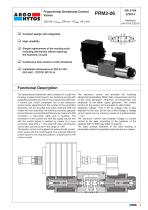
Proportional Directional Control Valves Size 06 · pmax 350 bar · Qmax 40 L/min Simple replacement of the exciting coils including electronics without opening the hydraulic circuits Continuous flow control in both directions High reliability Compact design with integrated Installation dimensions to DIN 24 340 / ISO 4401 / CETOP RP121-H Functional Description The proportional directional valve consists of a cast-iron housing, a special control spool, two centering springs with supporting washers and one or two proportional solenoids. A control box, which comprises one or two electronic control cards, depending on the number of the controlled solenoids, can be mounted onto either solenoid. With the model with two solenoids, the solenoid mounted apposite the control box is connected with the box by means of a DIN connector, a two-cored cable and a bushing. The connection of the control box with the supply source and with the control signal is realized by means of a 4-pin connector, type M12 x 1. The solenoid coils, including the o control box, can be turned in the range of ± 90 . The electric control unit supplies the solenoid with current, which varies with the control signal. The solenoid shifts the control spool to the required position, proportional to the control current. The electronic control unit provides the following adjustment possibilities: Offset, Gain, rise and drop-out time of the ramp generator, frequency (2 frequencies) and amplitude of the dither signal generator. The correct function of the control unit is signaled by LED-diodes. Stabilized voltage +10V (+5V for voltage 12V) is also available for the user. By the use of this voltage, a voltage control signal can be made by means of a potentiometer ³ 1 kW. The electronic control card enables voltage or current control to be used, according to the positions of the switches SW1 to SW3 (see table on page 6). The basic surface treatment of the valve housing is phosphate coated, the operating solenoids are zinc coated.
Open the catalog to page 1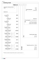
Ordering Code Proportional Directional Control Nominal size without designation without designation without electronics (supplied with counterpart) Nominal supply voltage Nominal flow rate at Ap = 10 bar Model for cylinders with asymmetric piston rod, piston area ratio 1:2
Open the catalog to page 2
Technical Data Nominal size Maximum operating pressure at ports P, A, B Maximum operating pressure at port T Hydraulic fluid Fluid temperature range (NBR / Viton) Ambient temperature, max. Viscosity range Maximum degree of fluid contamination 2 -1 Nominal flow rate Qn at Dp = 10 bar (n = 32 mm ×s ) Hysteresis Weight PRM2-062 PRM2-063 Mounting position Enclosure type EN 60 529 Technical Data of the Proportional Solenoid Type of coil Limit current 12 DC 24 DC 11.2 ... 14.7 20 ... 30 DC 5 DC (R > 1kW) 10 DC (R ³ 1kW) see table of switches configuration (page 6) 2.4 for R < 4W 1.5 for R < 10W 0.05...
Open the catalog to page 3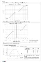
Flow Characteristic with Integrated Electronics 2 Flow Characteristic without Integrated Electronics 2 Values in parenthesis are valid for the supply voltage 12 V The coil current which initializes the flow through the proportional directional valve can differ due to the production tolerances about in a range of ± 6% of the limit current. 5% t4 Time t [ms] the control signal course of the integrated electronics Steady spool position ss [%] The values in table have only an informative character. The times of the transient characteristics at pressure or flow control will be in a particular hydraulic...
Open the catalog to page 4
Frequency Reponse
Open the catalog to page 5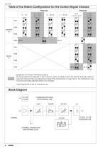
Table of the Switch Configuration for the Control Signal Choices PRM2-062 0 ... 5 V Designation of the basic manufacture setting. The ramp functions are adjusted on their minimum values, the dither is set to the optimal value with respect to hysteresis. Offset and Gain are adjusted according to the characteristic on page 3 and 4. The manufacturer does not recommend these adjusted values to be changed. * Input signal level for the 12 V electronic unit. STABILIZED VOLTAGE FOR EXTERNAL USE GAIN CONTROL CONNECTION MASTER AND SLAVE OUTPUT TO THE SOLENOID COIL
Open the catalog to page 6
Valve PRM2-062 (with one solenoid) 1.1 Control with external voltage source 0 ... 10 V (0 ... 5 V) or with external potentiometer R >1 kQ The control signal must have the same ground potential as the supply source. Master card for solenoid a (b) Wire colours (connection connector - electronics): amplitude - optimum Offset, Gain: according to the characteristics on page 3, 4
Open the catalog to page 7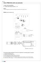
Valve PRM2-062 (with one solenoid) 2 Other control possibilities 2.1 Control with external source 0 ... 5 V The control signal must have the same ground potential as the supply source. MastGT card for solenoid a (b) For the factory setting modification for this case of application, the following steps are required: 1. Unscrew the electronics cover 2. Carefully remove the Master card 3. Flip the switch SW3 in position shown in the picture 4. Put in the Master card and fix the electronics cover 5. Connect the voltage +24 V from an external supply source to terminals 1 and 3 of the connector 6....
Open the catalog to page 8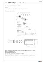
Valve PRM2-062 (with one solenoid) 2.2 Control with external source 0 ... 20 mA The control signal must have the same ground potential as the supply source. Master card for solenoid a (b) For the factory setting modification for this case of application, the following steps are required: 1. Unscrew the electronics cover 2. Carefully remove the Master card 3. Flip the switch SW1 and SW3 in position shown in the picture 4. Put in the Master card and fix the electronics cover 5. Connect the voltage +24 V (+12 V) from an external supply source to terminals 1 and 3 of the connector 6. Bring the control...
Open the catalog to page 9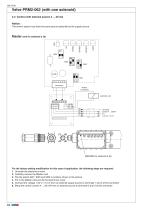
Valve PRM2-062 (with one solenoid) 2.3 Control with external source 4 ... 20 mA The control signal must have the same ground potential as the supply source. Master card for solenoid a (b) For the factory setting modification for this case of application, the following steps are required: 1. Unscrew the electronics cover 2. Carefully remove the Master card 3. Flip the switch SW1, SW2 and SW3 in position shown in the picture 4. Put in the Master card and fix the electronics cover 5. Connect the voltage +24 V (+12 V) from an external supply source to terminals 1 and 3 of the connector 6. Bring the...
Open the catalog to page 10All ARGO-HYTOS catalogs and technical brochures
 MLS3-06
10 Pages
 C5.3511 · C5.3516 · C5.3529
3 Pages
 LS 040 · LS 075
6 Pages
 ES 075
6 Pages
 Catalogue Hydraulic Drives
65 Pages
 Catalogue Filtration
342 Pages
 Catalogue Fluid Management
69 Pages
 Catalogue Lightline
50 Pages
 Filtration Guideline
20 Pages
 Off-line Filtration
2 Pages
 Light Line
4 Pages
 RC series
4 Pages
 TS3 MTS2
6 Pages
 ECOLINE
8 Pages


Archived catalogs
 TS4 MTS
6 Pages
 SR4P2-B2
4 Pages
 SR1P2-A2
4 Pages
 PRM7-10
10 Pages
 PRM8-06
4 Pages
 PRM2-04
20 Pages
 PRM6-10
20 Pages
 PRM7-06
10 Pages
 PRM7-04
10 Pages
 Coils
Coils18 Pages
 Datasheet RPEL1-06
6 Pages
 Datasheet RPH2-06
4 Pages
 Datasheet RPR3-04
4 Pages
 Solutions for clean Oil
6 Pages
 EXAPOR MAX 2
3 Pages
 Guidelines
21 Pages
 Brochure Wind Energy
2 Pages
 Agritechnica Highlights 2015
32 Pages
 MDA Highlights 2015
24 Pages
 Product summary
16 Pages
 Brochure for Endusers
2 Pages
 ARGO-HYTOS program summary
16 Pages


