Catalog excerpts

Nominal sizemm06 Max. operating pressure at ports P, A, Bbar320 Max. operating pressure at port Tbar160 Hydraulic fluidHydraulic oils of power classes HM, HV to CETOP - RP 91Hin viscosity classes ISO VG 32, 46 a 68. Fluid temperature range (NBR / Viton)C-30 ... +80-20 ... +80 Ambient temperature max.аCup to +50 Viscosity rangemm > 2 /s20 ... 400 Maximum degree of fluid contaminationClass 21/18/15 to ISO 4406 (1999). Nominal flow at ∆ p = 10 barL/min20 Hysteresis - open loop%< 6 Hysteresis - closed position loop%< 0.5 Weight- PRM5-062- PRM5-063kg2.22.7 Mounting positionoptional > Type of...
Open the catalog to page 3
(supply voltage 12V and 24V) Operating pressurebarmax. 320, staticElectric connectionelectrical connector G4W1F HirschmannContact assignment1 - operating voltage2 - output signal3 -ground4 -not usedEnclosure type to DIN 40050IP 65 Measured distancemm8 Operating voltageV9.6 ...30 DCLinearity error%< 1Current consumption at load current of 2 mAmA< 15Output voltageV0 ... 5Output signal range used:0 Position1 solenoid - displacement2.8 mm2 solenoids -displacement 2.8 mmV2.50.75 - 2.50.75 - 4.25Max. load currentmA2Noise voltage- at load current 0- at load current of 2 mAmV > p-p < 20<...
Open the catalog to page 4
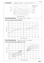
2 Measured at ν = 35 mm /sP → A / B → T or P → B / A → T Solenoid current:1 = 100% 2 = 80% > FlowQin[L/min] 3 = 60% 4 = 40% Input pressure p > o in [bar] > FlowQin[L/min] Control voltage u > x [%] > 2 Measured at ν = 35 mm /s, p > o - input pressure > FlowQin[L/min] p=10bar o p=320bar o p=20bar o p=160bar o p=50bar o Control voltage u > x [%] >
Open the catalog to page 5
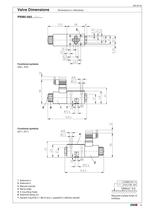
1 Solenoid a 2 Solenoid b 3 Manual overide 4 Name plate 5 4 mounting holes 6 Solenoid fixing nut 7 Square ring 9.25 x 1.68 (4 pcs.), supplied in delivery packet 8 Position sensor Required surface finish ofinterface. 9 Space required to remove connector >
Open the catalog to page 6
1 Solenoid a 2 Solenoid b 3 Name plate 4 4 mounting holes 5 Square ring 9.25 x 1.68 (4 pcs.), supplied in delivery packet 6 Position sensor Required surface finish ofinterface. 7 Space required to remove connector >
Open the catalog to page 7
1 Solenoid a 2 Solenoid b 3 Manual overide 4 Name plate 5 4 mounting holes 6 Solenoid fixing nut Required surface finish ofinterface. 7 Square ring 9.25 x 1.68 (4 pcs.), supplied in delivery packet >
Open the catalog to page 8
1 Solenoid a 2 Solenoid b 3 Manual overide 4 Name plate 5 4 mounting holes 6 Solenoid fixing nut Required surface finish ofinterface. 7 Square ring 9.25 x 1.68 (4 pcs.), supplied in delivery packet >
Open the catalog to page 9All ARGO-HYTOS catalogs and technical brochures
-
MLS3-06
10 Pages
-
C5.3511 · C5.3516 · C5.3529
3 Pages
-
LS 040 · LS 075
6 Pages
-
ES 075
6 Pages
-
Catalogue Hydraulic Drives
65 Pages
-
Catalogue Fluid Management
69 Pages
-
Filtration Guideline
20 Pages
-
Light Line
4 Pages
-
Off-line Filtration
2 Pages
-
Catalogue Filtration
342 Pages
-
Catalogue Lightline
50 Pages
-
RC series
4 Pages
-
TS3 MTS2
6 Pages
-
TS4 MTS
6 Pages
-
ECOLINE
8 Pages
-
SR4P2-B2
4 Pages
-
SR1P2-A2
4 Pages
-
PRM7-10
10 Pages
-
PRM8-06
4 Pages
-
PRM2-04
20 Pages
-
PRM6-10
20 Pages
-
PRM7-06
10 Pages
-
PRM2-06
20 Pages
-
PRM7-04
10 Pages
-
Coils
18 Pages
-
Datasheet RPEL1-06
6 Pages
-
Datasheet RPH2-06
4 Pages
-
Datasheet RPR3-04
4 Pages
Archived catalogs
-
MDA Highlights 2015
24 Pages
-
Solutions for clean Oil
6 Pages
-
Brochure for Endusers
2 Pages
-
Agritechnica Highlights 2015
32 Pages
-
Brochure Wind Energy
2 Pages
-
EXAPOR MAX 2
3 Pages
-
Guidelines
21 Pages
-
Product summary
16 Pages
-
ARGO-HYTOS program summary
16 Pages


