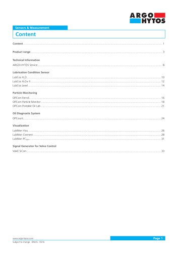
Catalog excerpts

Fluid Management Technical Handbook
Open the catalog to page 1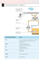
Contamination Ingress Dirt and water ingress from environment through worn seals Wear particles Damaged seal: Start up contamination, oil contamination from environment, dirt ingress during maintenance/repair, component breakdown, wear Leaking cooler, damaged seals, no/insufficient filler cap, condensation Product design, leaks, damaged seals, low oil level Blocked valve, damaged cooler Wrong fluid added to system Overstressed fluid
Open the catalog to page 6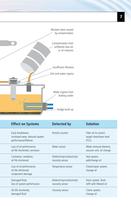
Blocked valve caused Contamination from Insufficient filtration Dirt and water ingress Water ingress from leaking cooler Early breakdown, increased wear, reduced system Particle counter target cleanliness level oil life shortened, corrosion Water sensor Water removal element, vacuum unit, oil change Cavitation, oxidation, component damage Damaged fluid, loss of system performance viscosity sensor Temperature sensor viscosity sensor Seal system, Check/repair system, Drain system, flush, refill with filtered oil damaged fluid Viscosity sensor Check system,
Open the catalog to page 7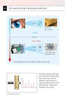
Visualizing Contamination Critical solid particles - Fine particles are not visible to the human eye. Particles passing through the laser beam block light from shining onto the particle size. Electronics Light blocking sensor
Open the catalog to page 8
bottles looks the same. dirtier than the other. Automatic particle counters give a fast, contamination picture Beating damaged Shaft damaged Damage caused Clutch case damaged by Oil mixture damage Bearing seal damaged oil aging causing floculation by microdiesel effect Source: KraussMaffei
Open the catalog to page 9
Water Content Water absorbing capacities of different fluid types Mineral oil containing Synthetic ester containing ppm = parts per million, 500 ppm = 0,51 water in 10001 oil Mineral oil Synthetic ester The water absorbing capacity varies from oil to oil. At saturation point (>100 % Relative humidity) free water will cause the fluid to have a cloudy appearance.
Open the catalog to page 10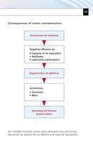
Consequences of water contamination • Lubrication performance System failure An installed moisture sensor gives early warning, permitting fast action to extend the oil lifetime and machine availability.
Open the catalog to page 11
Reason Product
Open the catalog to page 13
1.Stationary off-line filter systems Simply and rapidly fit to your existing systems. Get maximum fluid performance and lifetime with permanent off-line cleaning. Flow rates from 4 to 370 l/min, filter finenesses from 3 urn upwards. Water removal elements available. 2. Mobile filter systems Easy to use systems for through filter filling and cyclic cleaning with or without particle monitoring. Flow rates from 3 to 45 l/min, filter finesses from 3 urn upwards. Water removal elements available.
Open the catalog to page 14
3. Online oil condition monitors Prevent damage with early stage diagnosis by using OPCom for continuous real time online particle monitoring, OPCom AS for particle counting in aerated fluids, and LubCos H20+ for moisture content and oil ageing measurement. 4. Portable particle counters Our wide range of particle counter and monitors meet all your requirements. Use PODS Pro for bottle and online particle counting with viscosity and temperature measurement, in your lab or in field. Use OPCom Portable for plug and play online sampling, with built-in battery and memory, for day to day...
Open the catalog to page 15
Cleanliness Standards Counts/ml, Cumulative Although there is no direct relationship a rough guide can be found below. ISO 4406:1999 isa 3 digit code, representing the cumulative counts per ml at 4,6 and 14 ^m(c).The counts at each size are compared with the table to find the contamination code. The code is written as 3 numbers separated by a 7'. For example: 19/17/14. The first number represents the count at 4 um(c ), the second at 6 ^m(c ) and the third at 14 ^m(c ). More details can be found in ISO Standard
Open the catalog to page 16
>4rim(c) > 6 rJm(c) > 14 pjm(c) > 21 pjm(c) > 38 rtm(c) > 70 |jm(c) Size Code Data Is sorted Into cumulative particle counts per 100 ml, and is expressed either as the total number of particles for a given size (for example AS 4059 Class 6) or by designating a class for each size range (for Differential particle counts per 100 ml at various size ranges. For example, for a classification of NAS 6, the particle counts In each particle size range must be below the counts/100 ml shown In the table for NAS class 6. * Classes and contamination limits Identical to NAS 1638.
Open the catalog to page 17
Target Cleanliness Levels Recommended Target Cleanliness Levels (TCL) for different system components. If the operating pressure is increased in a system, it is necessary to improve the oil cleanliness in order to achieve the same wear lifetime for the components. By improving system cleanliness the lifetime of the hydraulic or lubrication system
Open the catalog to page 18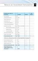
Return on Investment Calculation Fluid service will prevent up to 80 % of fluid related failures leaving 20 %
Open the catalog to page 19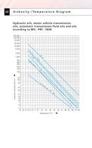
V i s k o s i t y - / Te m p e r a t u r e D i a g r a m Hydraulic oils, motor vehicle transmission oils, automatic transmission fluid oils and oils according to MIL - PRF - 5606 200,000 100,000 50,000 20,000 10,000 5,000 H -L /H 2,000 E9 0 0 AT E8 8x SA F H -L /H -L P4 6 100 P6 500 400 300 200 150 SA -L 1,000 50 40 30 ac co rdi 20 16 ng to MI L- PR F- 12 10 9 8 7 6 06 -L /H -L P3 2 5 -25 -20 -15 -10 -5 0 5 10 56 H kinematic viscosity [mm2/s] 22 20 30 40 temperature [°C] 50 60 70 80 90 100 110 120
Open the catalog to page 22
ARGO-HYTOS subsidiaries China ARGO-HYTOS Fluid Power Systems Czech Republic ARGO-HYTOS s.r.o. ARGO-HYTOS SARL ARGO-HYTOS GMBH Great Britain ARGO-HYTOS Ltd. Poland ARGO-HYTOS Scandinavia ARGO-HYTOS NordicAB Distribution partners Find our worldwide distribution partners at www.argo-hytos.com
Open the catalog to page 24All ARGO-HYTOS catalogs and technical brochures
-
MLS3-06
10 Pages
-
C5.3511 · C5.3516 · C5.3529
3 Pages
-
LS 040 · LS 075
6 Pages
-
ES 075
6 Pages
-
Catalogue Hydraulic Drives
65 Pages
-
Catalogue Fluid Management
69 Pages
-
Filtration Guideline
20 Pages
-
Light Line
4 Pages
-
Off-line Filtration
2 Pages
-
Catalogue Filtration
342 Pages
-
Catalogue Lightline
50 Pages
-
RC series
4 Pages
-
TS3 MTS2
6 Pages
-
TS4 MTS
6 Pages
-
ECOLINE
8 Pages
-
SR4P2-B2
4 Pages
-
SR1P2-A2
4 Pages
-
PRM7-10
10 Pages
-
PRM8-06
4 Pages
-
PRM2-04
20 Pages
-
PRM6-10
20 Pages
-
PRM7-06
10 Pages
-
PRM2-06
20 Pages
-
PRM7-04
10 Pages
-
Coils
18 Pages
-
Datasheet RPEL1-06
6 Pages
-
Datasheet RPH2-06
4 Pages
-
Datasheet RPR3-04
4 Pages
Archived catalogs
-
MDA Highlights 2015
24 Pages
-
Solutions for clean Oil
6 Pages
-
Brochure for Endusers
2 Pages
-
Agritechnica Highlights 2015
32 Pages
-
Brochure Wind Energy
2 Pages
-
EXAPOR MAX 2
3 Pages
-
Guidelines
21 Pages
-
Product summary
16 Pages
-
ARGO-HYTOS program summary
16 Pages


