
- Catalogs
- Arcus Technology
- pmx-4et-sa

- Products
- Catalogs
- News & Trends
- Exhibitions
pmx-4et-sa
1 / 108 PagesView full catalog
pmx-4et-sa
Product catalog summary
Introduction
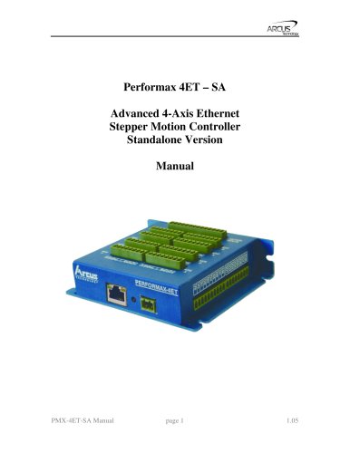
The PMX-4ET-SA is a sophisticated 4-axis Ethernet stepper motion controller designed for standalone operation, capable of executing programs independently of a host through Ethernet communication.
The PMX-4ET-SA is a sophisticated 4-axis Ethernet stepper motion controller designed for standalone operation, capable of executing programs independently of a host through Ethernet communication.
Features
- Ethernet communication at 10Mbps using Arcus ASCII command.
- Standalone programmability with a maximum pulse output rate of 6M PPS.
- Supports trapezoidal or s-curve acceleration and on-the-fly speed changes.
- Capable of XYZU linear, XY circular, and XY arc coordinated motions.
- Continuous linear coordinated buffered moves with a buffer size of 36.
- A/B/Z differential encoder inputs with a maximum frequency of 5 MHz.
- StepNLoop closed-loop control for position verification.
- Opto-isolated I/O with 8 inputs and 8 outputs.
- Various homing routines including high-speed, low-speed, limit-only, and Z-index encoder channel options.
Applications
Ideal for 3D CAD/CAM, engraving, laser cutting, and dispensing.
Ideal for 3D CAD/CAM, engraving, laser cutting, and dispensing.
Model Numbers and Top Board Options
Available with Standard Top Board (PMX-4ET-SA-TBS) and DB9 Top Board (PMX-4ET-SA-TB9).
Available with Standard Top Board (PMX-4ET-SA-TBS) and DB9 Top Board (PMX-4ET-SA-TB9).
Electrical Specifications
- Controller Power Requirement: +12 to +24 VDC, 1.5A peak.
- Driver Power Requirement: +12 to +48 VDC, 3.0A peak.
- Operating Temperature: -20°C to +80°C; Storage Temperature: -55°C to +150°C.
- Pulse, Dir, Enable Outputs: Open-collector output, max sink voltage +24 VDC, max sink current 40 mA.
- Digital Inputs: Opto-isolated, voltage range +12V to +24VDC, max forward current 40 mA.
- Digital Outputs: Opto-isolated Darlington outputs, max voltage +12V to +24VDC, max source current 90 mA.
- Alarm Input: TTL, voltage +0 to +5VDC.
Dimensions and Connections
Consistent dimensions across models with specific connector configurations depending on the top board type.
Consistent dimensions across models with specific connector configurations depending on the top board type.
Contacting Support
For technical support, contact [email protected] or your local distributor.
For technical support, contact [email protected] or your local distributor.
Connector Specifications
- DIO 10-Pin Connector: For digital inputs with a supply voltage of +12V to +24VDC.
- DIO 8-Pin Connector: For digital outputs.
- Motion Inputs 14-Pin Connector: Handles limit and home inputs for axes.
- Encoder Signals 8-Pin Connector: Manages encoder inputs with a +5V supply.
- TB9 Axis Signals DB9 Connector: Used for driver power and control signals.
Interface Circuit
Includes pulse, direction, and enable outputs, which are open collector outputs capable of sinking up to 40mA of current.
Includes pulse, direction, and enable outputs, which are open collector outputs capable of sinking up to 40mA of current.
Inputs and Outputs
- Limit, Home, and Digital Inputs: Require an opto-isolated voltage supply.
- Digital Outputs: Source from VS when the signal is turned on.
Getting Started
Guidance on setting up the PMX-4ET-SA, including point-to-point and network-based configurations.
Guidance on setting up the PMX-4ET-SA, including point-to-point and network-based configurations.
Windows GUI Features
- Program & Control: Allows interactive testing and programming.
- DXF Converter: Converts DXF files to motion commands.
- Graphical Converter: Enables graphical creation of standalone programs.
Main Control Screen
Displays status and control options for motor positions, speeds, and statuses.
Displays status and control options for motor positions, speeds, and statuses.
On-The-Fly Controls
Provides options for speed and position adjustments during operation.
Provides options for speed and position adjustments during operation.
Standalone Program Features
Includes program file control, editor, and control options for running, stopping, and pausing programs.
Includes program file control, editor, and control options for running, stopping, and pausing programs.
Setup and Configuration
Details settings for polarity, auto-run, StepNLoop parameters, and IP address configuration.
Details settings for polarity, auto-run, StepNLoop parameters, and IP address configuration.
Terminal and Variable Status
Offers command line interface for sending commands and monitoring variable statuses.
Offers command line interface for sending commands and monitoring variable statuses.
About Section
Displays software and firmware version information.
Displays software and firmware version information.
DXF Converter Overview
Instructions on using the DXF Viewer and managing DXF files, including setting parameters for scaling, speed, and routines for pen up/down actions.
Instructions on using the DXF Viewer and managing DXF files, including setting parameters for scaling, speed, and routines for pen up/down actions.
Graphical Programmer
Describes the use of the Graphical Programmer for executing continuous loops and setting speed, move commands, and other motion control features.
Describes the use of the Graphical Programmer for executing continuous loops and setting speed, move commands, and other motion control features.
Motion Control Feature Overview
Supports trapezoidal and S-curve velocity profiles, with commands for setting high/low speeds and acceleration/deceleration times.
Supports trapezoidal and S-curve velocity profiles, with commands for setting high/low speeds and acceleration/deceleration times.
Arc and Circular Moves
Commands for drawing arcs in both clockwise and counterclockwise directions using absolute and relative angles.
Commands for drawing arcs in both clockwise and counterclockwise directions using absolute and relative angles.
Buffered Linear Interpolation Moves
Supports buffered linear coordinated motions for X, Y, and Z-axes with constant speed settings.
Supports buffered linear coordinated motions for X, Y, and Z-axes with constant speed settings.
On-The-Fly Target Position Change
Allows changing the target position during motion.
Allows changing the target position during motion.
Homing Routines
Four homing modes with specific sequences for setting the motor position to zero.
Four homing modes with specific sequences for setting the motor position to zero.
Jogging and Stopping
Commands for jogging and halting motor movement.
Commands for jogging and halting motor movement.
Polarity and Position Reading
Commands for setting signal polarity and reading motor and encoder positions.
Commands for setting signal polarity and reading motor and encoder positions.
Limits and Alarms
Handling limit and alarm errors, including clearing them with specific commands.
Handling limit and alarm errors, including clearing them with specific commands.
Digital Inputs/Outputs
Controlled via DI and DO commands, with initial states set with DOBOOT and EOBOOT registers.
Controlled via DI and DO commands, with initial states set with DOBOOT and EOBOOT registers.
Synchronization Outputs
Triggered based on encoder positions, with conditions set using SYN commands.
Triggered based on encoder positions, with conditions set using SYN commands.
StepNLoop Closed Loop Control
Uses an incremental encoder for position verification and correction.
Uses an incremental encoder for position verification and correction.
Specifications and Procedures
- Speed and Interpolation: Speed is measured in encoder counts per second for individual axis moves.
- Device IP Address: Default IP address is 192.168.1.250 with port 5001.
- Standalone Programming: Supports standalone programs with a memory size of 7,650 assembly lines.
- Boot-up Sequence: Takes approximately 5 seconds to boot up.
- Hard Reset: Involves a specific sequence of digital input signals to reset flash memory to factory defaults.
Communication Protocol
- Ethernet Communication: Uses 10Mbps Ethernet ASCII communication over TCP/IP.
- ASCII Language Specification: Commands include ABORT for stopping motors, ACC for setting acceleration values, and various commands for controlling motor movements and settings.
Key Tables and Charts
- Hard Reset Step Input Conditions: Details the sequence of digital input signals required for a hard reset.
- ASCII Command Descriptions: Lists commands and their functions.
Key Sections
- Standalone Line Commands: Commands for managing standalone lines and s-curve controls.
- StepNLoop Parameters: Commands for setting and returning values related to StepNLoop.
- Speed and Motion Control: Commands for managing speed changes and motion control.
- Synchronization and Triggering: Commands for configuring sync outputs and trigger positions.
- Error Handling: Error codes for diagnosing issues with command processing.
- Programming Constructs: Includes programming constructs for creating complex motion control programs.
Critical Information
- Command Syntax: Each command has a specific syntax that must be followed.
- Parameter Ranges: Defined ranges for parameters such as acceleration values and high-speed settings.
- Error Codes: Understanding error codes is crucial for troubleshooting.
- Best Practices: Proper use of commands can optimize performance and prevent errors.
Example Programs
- Standalone Example Program 5: Increment the motor by 1000 whenever the DI1 rising edge is detected.
- Standalone Example Program 6: Move to specific positions based on digital input signals.
- Standalone Example Program 7: Program 0 moves motor between positions 0 and 1000, while Program 1 controls Program 0 using digital inputs.
- Standalone Example Program 8: Program 0 moves motor between positions 0 and 1000, Program 1 monitors communication time-out and manages errors.
Appendix A: Speed Settings
- Speed and Acceleration: Details on setting high speed and low speed values.
- Formulas: Max ACC = ((HS – LS) / δ) × 1000 [ms].
- Examples: Calculations for different HSPD and LSPD values provided.
Contact Information
Arcus Technology, Inc.
3159 Independence Dr, Livermore, CA 94551
Phone: 925-373-8800
Website: www.arcustechnology.com
Arcus Technology, Inc.
3159 Independence Dr, Livermore, CA 94551
Phone: 925-373-8800
Website: www.arcustechnology.com
See more
All Arcus Technology catalogs and technical brochures
 ARCUS MOTION PRODUCT CATALOG
43 Pages
Archived catalogs
 pmx-4ex-sa
119 Pages
 pmx-4cx-sa
60 Pages
 pmx-2ex-sa
79 Pages
 pmx-2ed-sa
78 Pages
 ace-sxe
88 Pages
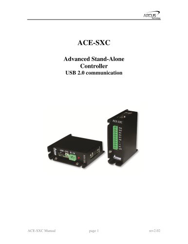 ace-sxc
66 Pages
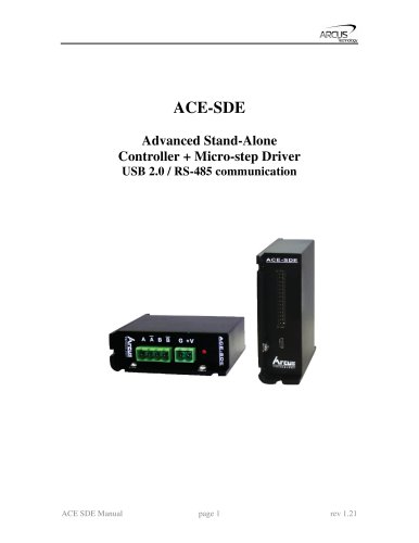 ace-sde
88 Pages
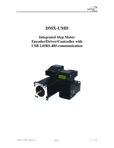 dmx-umd
87 Pages
 dmx-k-drv
32 Pages
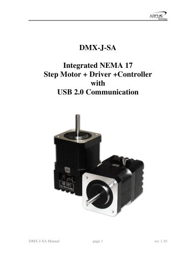 dmx-j-sa
58 Pages
 dmx-eth
78 Pages
 dmx-a2-drv
26 Pages
Related Searches
- Electromotor
- DC electromotor
- Multipole motor
- 24 V motor
- 2-pole motor
- Stepper motor
- Motor controller
- 48 V motor
- Stepper motor controller
- Integrated-drive motor
- Programmable motor controller
- Closed-loop motor controller
- Motor with integrated controller
- Single-axis motor controller
- Development kit
- Microstepping motor controller
- Multi-axis motor controller
- 2-axis motor controller
*Prices are pre-tax. They exclude delivery charges and customs duties and do not include additional charges for installation or activation options. Prices are indicative only and may vary by country, with changes to the cost of raw materials and exchange rates.
About DirectIndustry
DirectIndustry is a marketplace that offers B2B players a complete experience, from product sourcing to purchase. DirectIndustry is an entity of VirtualExpo Group.
Are you a buyer?
Are you a supplier?