
- Catalogs
- Arcus Technology
- pmx-2ex-sa

- Products
- Catalogs
- News & Trends
- Exhibitions
pmx-2ex-sa
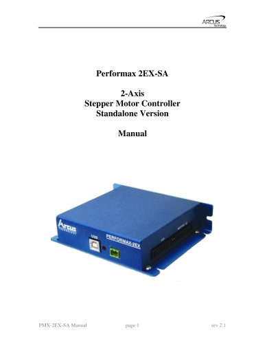
1 / 79 PagesView full catalog
pmx-2ex-sa
Product catalog summary
Introduction
The PMX-2EX-SA is a 2-axis programmable stepper motor controller that can function independently or through USB communication. It supports standalone programming, with a pulse output rate of up to 6M PPS, and features trapezoidal or s-curve acceleration, and XY linear coordinated motion. It includes A/B/Z differential encoder inputs and StepNLoop closed-loop control for position verification, along with opto-isolated I/O with 8 inputs and outputs, and various homing routines.
The PMX-2EX-SA is a 2-axis programmable stepper motor controller that can function independently or through USB communication. It supports standalone programming, with a pulse output rate of up to 6M PPS, and features trapezoidal or s-curve acceleration, and XY linear coordinated motion. It includes A/B/Z differential encoder inputs and StepNLoop closed-loop control for position verification, along with opto-isolated I/O with 8 inputs and outputs, and various homing routines.
Electrical Specifications
The controller requires a regulated voltage of +12 to +24 VDC and can handle a peak current of 1.5A. It operates within a temperature range of -20°C to +80°C and can be stored between -55°C and +150°C. The pulse, direction, and enable outputs are open-collector types with a maximum sink voltage of +24 VDC and a current of 40 mA. Digital inputs and outputs are opto-isolated, supporting a voltage range of +12V to +24VDC.
The controller requires a regulated voltage of +12 to +24 VDC and can handle a peak current of 1.5A. It operates within a temperature range of -20°C to +80°C and can be stored between -55°C and +150°C. The pulse, direction, and enable outputs are open-collector types with a maximum sink voltage of +24 VDC and a current of 40 mA. Digital inputs and outputs are opto-isolated, supporting a voltage range of +12V to +24VDC.
Connections
The PMX-2EX-SA uses a 2-pin connector for power input and a 50-pin connector for control and encoder I/O. The 50-pin motion I/O includes inputs for limit and home signals for both X and Y axes, as well as digital inputs and outputs.
The PMX-2EX-SA uses a 2-pin connector for power input and a 50-pin connector for control and encoder I/O. The 50-pin motion I/O includes inputs for limit and home signals for both X and Y axes, as well as digital inputs and outputs.
Getting Started
The manual provides guidance on setting up the device, including typical configurations and the main control screen interface.
The manual provides guidance on setting up the device, including typical configurations and the main control screen interface.
Motion Control Overview
This section covers motion profiles, pulse speed, on-the-fly speed changes, motor status, and various motion commands such as homing, jogging, and stopping. It also details the use of digital and analog inputs/outputs and joystick control.
This section covers motion profiles, pulse speed, on-the-fly speed changes, motor status, and various motion commands such as homing, jogging, and stopping. It also details the use of digital and analog inputs/outputs and joystick control.
Communication
The PMX-2EX-SA supports USB communication with API functions and addresses potential communication issues.
The PMX-2EX-SA supports USB communication with API functions and addresses potential communication issues.
Language Specifications
The manual includes detailed specifications for ASCII and standalone programming languages, including error codes and command syntax.
The manual includes detailed specifications for ASCII and standalone programming languages, including error codes and command syntax.
Example Programs
Several standalone example programs are provided to demonstrate single and multi-threaded operations.
Several standalone example programs are provided to demonstrate single and multi-threaded operations.
Appendix
The appendix includes information on speed settings and acceleration/deceleration ranges.
The appendix includes information on speed settings and acceleration/deceleration ranges.
Specifications and Connector Details
The document outlines the specifications for digital outputs and connectors, listing digital outputs DO4 to DO8 and mentioning several 'No Connection' pins. The mating connector is a 50-pin 0.1" connector manufactured by CW Industries, part number C3AAG-5018M. Other compatible IDC connectors can also be used.
The document outlines the specifications for digital outputs and connectors, listing digital outputs DO4 to DO8 and mentioning several 'No Connection' pins. The mating connector is a 50-pin 0.1" connector manufactured by CW Industries, part number C3AAG-5018M. Other compatible IDC connectors can also be used.
Interface Circuit and Outputs
The manual describes the interface circuit for the PMX-2EX-SA, detailing pulse/dir/enable outputs which are open collector outputs capable of sinking up to 40mA at 24VDC. Digital outputs are opto-isolated using Darlington transistors, capable of sinking up to 100mA at 24VDC. Digital inputs require an opto-supply input of 12 to 24VDC.
The manual describes the interface circuit for the PMX-2EX-SA, detailing pulse/dir/enable outputs which are open collector outputs capable of sinking up to 40mA at 24VDC. Digital outputs are opto-isolated using Darlington transistors, capable of sinking up to 100mA at 24VDC. Digital inputs require an opto-supply input of 12 to 24VDC.
Encoder and Analog Inputs
Encoder inputs can be connected using differential or single-ended connectors. Analog inputs range from 0 to 5V with a 10-bit resolution, allowing joystick control. The maximum source current for analog inputs is 10mA.
Encoder inputs can be connected using differential or single-ended connectors. Analog inputs range from 0 to 5V with a 10-bit resolution, allowing joystick control. The maximum source current for analog inputs is 10mA.
Control and Setup
The manual provides detailed instructions on setting up and controlling the PMX-2EX-SA, including setting speed, acceleration, and homing parameters. It explains the use of global and individual speed settings, and how to perform on-the-fly speed and position changes.
The manual provides detailed instructions on setting up and controlling the PMX-2EX-SA, including setting speed, acceleration, and homing parameters. It explains the use of global and individual speed settings, and how to perform on-the-fly speed and position changes.
Motion Control Overview
The PMX-2EX-SA uses a trapezoidal velocity profile by default, with options for an S-curve profile. Commands for setting high and low speeds, acceleration, and deceleration are provided. The document also covers motor status monitoring and error handling.
The PMX-2EX-SA uses a trapezoidal velocity profile by default, with options for an S-curve profile. Commands for setting high and low speeds, acceleration, and deceleration are provided. The document also covers motor status monitoring and error handling.
Homing and Movement Commands
Homing routines involve moving the motor towards home or limit switches. The document describes various homing commands and routines, including high-speed and low-speed homing.
Homing routines involve moving the motor towards home or limit switches. The document describes various homing commands and routines, including high-speed and low-speed homing.
Programming and Control
The manual includes sections on programming the PMX-2EX-SA, with details on compiling and downloading code, managing program files, and controlling standalone programs. It provides a comprehensive guide to using the terminal for command input and output.
The manual includes sections on programming the PMX-2EX-SA, with details on compiling and downloading code, managing program files, and controlling standalone programs. It provides a comprehensive guide to using the terminal for command input and output.
Motor Control Procedures
- Homing Routine: The motor starts at low speed, accelerates to high speed, and upon triggering the home input, resets the position counter to zero. It decelerates, reverses direction to find the home switch, and continues past it by a defined home correction amount (HCA) before returning to the home switch at low speed.
- Limit Homing: Initiated by a limit home command, the motor accelerates to high speed, stops when the limit is triggered, reverses direction by a limit correction amount (LCA), and reaches the zero position.
- Home and Z-index: The motor accelerates to high speed, decelerates upon home input trigger, searches for the z-index pulse, and stops to set the position to zero.
- Z-index Only: The motor starts at low speed, stops upon finding the z-index pulse, and sets the position to zero.
- Jogging: Continuous speed operation is available using specific commands for synchronous motor jogging.
- Stopping: The ABORT command stops all axes immediately, while the STOP command allows for deceleration before stopping.
- Position Reading: Motor and encoder positions can be read using specific commands, with manual setting options available unless StepNLoop is enabled.
- Polarity Settings: Polarity can be adjusted using commands, with specific bit representations for various functions.
- Limit Switches: Triggering a limit switch stops the motor and sets a limit error status, which can be cleared with a command. Errors can be ignored by setting a specific parameter.
- Error Handling: Errors during standalone execution trigger a jump to a subroutine or halt execution, depending on configuration.
- Digital I/O: The module includes 8 digital inputs and outputs, with commands to read and set their status. Initial states can be stored in flash memory.
- Analog Inputs: Two 10-bit analog inputs are available, with a range of 0-5000 mV.
- Functionality: Joystick control allows for speed and direction control via analog inputs, with parameters for speed, tolerance, and limits.
- Parameters: Various parameters define maximum speed, speed change, zero tolerance, and limits for joystick control.
- Functionality: This feature provides position verification and delta monitoring, stopping the motor if errors exceed defined ranges.
- Parameters: Includes ratio, tolerance, error range, and correction attempt settings.
- Device Number: The device number can be set and stored in flash memory, taking effect after a power cycle.
- Standalone Programs: Supports multi-threading and error handling, with options for running programs on boot-up and storing configurations to flash.
Specifications:
The PMX-2EX-SA manual outlines various parameters and settings for the device, including StepNLoop parameters, joystick settings, and USB communication protocols. It specifies that the device is USB 2.0 compliant and can communicate with a PC using Windows-compatible DLL API function calls. The typical communication transaction time is in single-digit milliseconds, depending on the CPU speed and command type.
The PMX-2EX-SA manual outlines various parameters and settings for the device, including StepNLoop parameters, joystick settings, and USB communication protocols. It specifies that the device is USB 2.0 compliant and can communicate with a PC using Windows-compatible DLL API function calls. The typical communication transaction time is in single-digit milliseconds, depending on the CPU speed and command type.
Communication Procedures:
The manual provides detailed instructions for USB communication, including functions to get the number of devices, open and close communication, set timeouts, send and receive commands, and flush communication buffers. It highlights common USB communication issues, such as data buffer synchronization problems, and suggests solutions like buffer flushing and using a USB cable with a noise suppression choke.
The manual provides detailed instructions for USB communication, including functions to get the number of devices, open and close communication, set timeouts, send and receive commands, and flush communication buffers. It highlights common USB communication issues, such as data buffer synchronization problems, and suggests solutions like buffer flushing and using a USB cable with a noise suppression choke.
ASCII Language Specification:
The document describes various ASCII commands for controlling the PMX-2EX-SA, including commands for aborting movements, setting acceleration and deceleration values, and managing digital inputs and outputs. It also covers homing operations, joystick control, and StepNLoop control settings.
The document describes various ASCII commands for controlling the PMX-2EX-SA, including commands for aborting movements, setting acceleration and deceleration values, and managing digital inputs and outputs. It also covers homing operations, joystick control, and StepNLoop control settings.
Error Codes:
The manual lists potential error codes that may be returned if an ASCII command cannot be processed. These include errors related to invalid commands, out-of-range parameters, and uninitialized subroutines.
The manual lists potential error codes that may be returned if an ASCII command cannot be processed. These include errors related to invalid commands, out-of-range parameters, and uninitialized subroutines.
Standalone Language Specification:
The standalone language section provides syntax and examples for programming the PMX-2EX-SA. It includes commands for motion control, acceleration settings, and conditional statements. Comments are denoted by a semicolon and must be on their own line.
The standalone language section provides syntax and examples for programming the PMX-2EX-SA. It includes commands for motion control, acceleration settings, and conditional statements. Comments are denoted by a semicolon and must be on their own line.
Key Recommendations:
- Ensure USB cables have noise suppression chokes to prevent communication issues.
- Use the latest PerformaxCom.dll for improved functionality, such as buffer flushing.
- Regularly check for proper replies to commands to avoid synchronization issues.
- Store device settings to flash memory to retain configurations after reboot.
- Ensure USB cables have noise suppression chokes to prevent communication issues.
- Use the latest PerformaxCom.dll for improved functionality, such as buffer flushing.
- Regularly check for proper replies to commands to avoid synchronization issues.
- Store device settings to flash memory to retain configurations after reboot.
Acceleration and Deceleration: The document provides commands for setting and reading acceleration (ACC) and deceleration (DEC) values for different axes. These values are expressed in milliseconds. Conditional statements can be used to check these values.
Analog and Digital Inputs: The PMX-2EX-SA has 2 analog inputs and 8 digital inputs. Analog inputs range from 0-5000 mV. Syntax for reading and conditional checks are provided.
Delay and Abort Commands: Delays can be set in milliseconds, and the ABORT command stops all axes with deceleration.
Digital Outputs: The device has 8 digital outputs. Commands for reading and setting these outputs are detailed, along with conditional checks.
Encoder Position: Commands for reading and setting the current encoder position (E[axis]) are provided, along with examples.
Conditional Logic: The document outlines the use of IF, ELSE, and ELSEIF statements for conditional operations, including syntax and examples.
Subroutines and Program Control: Commands for defining and calling subroutines (GOSUB, ENDSUB) and program control (PRG, END) are explained.
Homing and Speed Control: Commands for homing (HOME, HLHOME, LHOME) and setting high and low speeds (HSPD, LSPD) are included, with syntax and examples.
Joystick Control: Various commands for joystick control, including enabling the joystick, setting speed, and defining limits, are detailed.
Motor and Pulse Position: Commands for getting motor status (MST) and pulse position (P[axis], PS[axis]) are provided.
S-Curve and StepNLoop Control: Commands for enabling S-Curve (SCV[axis]) and StepNLoop (SL[axis], SLS[axis]) are included, with notes on limitations.
Overview: This document provides detailed instructions and examples for programming and controlling motor movements using the PMX-2EX-SA system. It includes syntax, examples, and explanations for various commands and settings.
Key Sections:
1. Command Descriptions: The document outlines several commands used to control motor movements, including:
- SR[0,1]: Sets standalone control for specified programs.
- SSPD[axis]: Allows on-the-fly speed changes for individual axes, with a range from 1 to 6,000,000 PPS.
- SSPDM[axis]: Sets individual on-the-fly speed change mode, ranging from 0 to 9.
- STOP: Stops all axes or individual axes with deceleration.
- STORE: Saves device settings and variables to flash memory.
- SUB: Indicates the start of a subroutine, with subroutine 31 reserved for error handling.
- TOC: Sets the communication time-out parameter in milliseconds.
- V: Assigns values to variables, with operations like addition, subtraction, and bitwise operations.
- WAIT: Pauses program execution until a move on a specified axis is complete.
- WHILE: Executes a loop based on specified conditions.
- X and Y: Commands for moving the X and Y axes to target locations, with options for linear interpolation.
- ZHOME and ZOME: Commands for homing and zooming axes using current speed and acceleration settings.
2. Example Standalone Programs: The document provides several example programs demonstrating different tasks, such as moving motors between positions, using subroutines, and handling digital inputs and outputs.
3. Speed Settings: Detailed tables and formulas are provided for setting high speed (HSPD), low speed (LSPD), and acceleration (ACC) values. The document explains how to calculate maximum allowable acceleration based on speed settings.
4. Acceleration/Deceleration Range: The document explains how the controller calculates acceleration and deceleration for positional moves, including conditions for using triangle velocity profiles.
Contact Information: Arcus Technology, Inc. contact details are provided for further inquiries.
Conclusion: This document serves as a comprehensive guide for programming and controlling motor movements using the PMX-2EX-SA system, with detailed command descriptions, examples, and technical specifications.
See more
All Arcus Technology catalogs and technical brochures
 ARCUS MOTION PRODUCT CATALOG
43 Pages
Archived catalogs
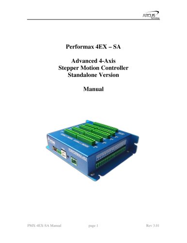 pmx-4ex-sa
119 Pages
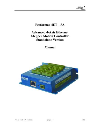 pmx-4et-sa
108 Pages
 pmx-4cx-sa
60 Pages
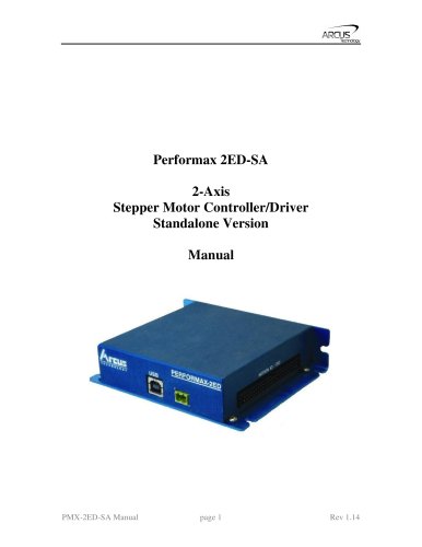 pmx-2ed-sa
78 Pages
 ace-sxe
88 Pages
 ace-sxc
66 Pages
 ace-sde
88 Pages
 dmx-umd
87 Pages
 dmx-k-drv
32 Pages
 dmx-j-sa
58 Pages
 dmx-eth
78 Pages
 dmx-a2-drv
26 Pages
Related Searches
- Electromotor
- DC electromotor
- Multipole motor
- 24 V motor
- 2-pole motor
- Motor controller
- 48 V motor
- Stepper motor controller
- Integrated-drive motor
- Programmable motor controller
- Closed-loop motor controller
- Motor with integrated controller
- Single-axis motor controller
- Development kit
- Microstepping motor controller
- Multi-axis motor controller
- 2-axis motor controller
*Prices are pre-tax. They exclude delivery charges and customs duties and do not include additional charges for installation or activation options. Prices are indicative only and may vary by country, with changes to the cost of raw materials and exchange rates.
About DirectIndustry
DirectIndustry is a marketplace that offers B2B players a complete experience, from product sourcing to purchase. DirectIndustry is an entity of VirtualExpo Group.
Are you a buyer?
Are you a supplier?