
- Catalogs
- Arcus Technology
- dmx-j-sa

- Products
- Catalogs
- News & Trends
- Exhibitions
dmx-j-sa
1 / 58 PagesView full catalog
dmx-j-sa
Product catalog summary
Introduction
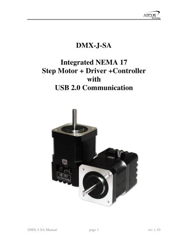
The DMX-J-SA is an integrated step motor with a microstep driver and controller, featuring USB 2.0 communication. It supports standalone programming, allowing independent operation from a host. Compatible with Windows and Linux, it includes drivers and sample source code for software development.
The DMX-J-SA is an integrated step motor with a microstep driver and controller, featuring USB 2.0 communication. It supports standalone programming, allowing independent operation from a host. Compatible with Windows and Linux, it includes drivers and sample source code for software development.
Features
- USB 2.0 communication
- Stand-alone programmable
- 16 microstep driver with peak current from 100mA to 2.0A
- NEMA 17 stepper motor
- Opto-isolated I/O with 2 inputs and 2 outputs
- Homing routines including high-speed and limit-only options
- 12-24 VDC voltage input
- USB 2.0 communication
- Stand-alone programmable
- 16 microstep driver with peak current from 100mA to 2.0A
- NEMA 17 stepper motor
- Opto-isolated I/O with 2 inputs and 2 outputs
- Homing routines including high-speed and limit-only options
- 12-24 VDC voltage input
Specifications
The DMX-J-SA operates on a regulated supply voltage range of +12 to 24 VDC with a recommended current of 2.0 Amp. The operating temperature ranges from 0°C to +85°C, while the storage temperature ranges from -55°C to +150°C. Digital inputs are opto-isolated NPN inputs with a supply of +12 to +24 VDC, and digital outputs are opto-isolated open-collector PNP outputs with a maximum voltage of +24VDC.
The DMX-J-SA operates on a regulated supply voltage range of +12 to 24 VDC with a recommended current of 2.0 Amp. The operating temperature ranges from 0°C to +85°C, while the storage temperature ranges from -55°C to +150°C. Digital inputs are opto-isolated NPN inputs with a supply of +12 to +24 VDC, and digital outputs are opto-isolated open-collector PNP outputs with a maximum voltage of +24VDC.
Dimensions
The NEMA 17 models have specific dimensions: DMX-J-SA-17-2 (double stack) is 1.58 inches, and DMX-J-SA-17-3 (triple stack) is 1.89 inches.
The NEMA 17 models have specific dimensions: DMX-J-SA-17-2 (double stack) is 1.58 inches, and DMX-J-SA-17-3 (triple stack) is 1.89 inches.
Connectors
The device includes a 10-pin connector for digital inputs and outputs, and a 4-pin connector for motor windings. The USB connector is a Mini-B to A type.
The device includes a 10-pin connector for digital inputs and outputs, and a 4-pin connector for motor windings. The USB connector is a Mini-B to A type.
Power Input
The power input requires a regulated supply voltage of +12 to 24 VDC with a recommended current of 2.0 Amp.
The power input requires a regulated supply voltage of +12 to 24 VDC with a recommended current of 2.0 Amp.
Driver Current
The microstep value is fixed at 16 microsteps. The driver current ranges from 100 mAmp to 2.0 Amp, with specific settings for different models to prevent overheating.
The microstep value is fixed at 16 microsteps. The driver current ranges from 100 mAmp to 2.0 Amp, with specific settings for different models to prevent overheating.
Operating Temperature
The maximum ambient operating temperature is 85°C. The device should be mounted to a metallic bracket for heat dissipation.
The maximum ambient operating temperature is 85°C. The device should be mounted to a metallic bracket for heat dissipation.
Getting Started
The DMX-J-SA can be controlled via a Windows GUI program, which requires proper USB driver installation. The GUI provides various controls for motor status, motor control, digital input/output status, and program management.
The DMX-J-SA can be controlled via a Windows GUI program, which requires proper USB driver installation. The GUI provides various controls for motor status, motor control, digital input/output status, and program management.
Motion Control Overview
The DMX-J-SA uses a trapezoidal velocity profile for motion control, with a position counter range from -2,147,483,648 to 2,147,483,647. It supports both incremental and absolute move modes, with specific commands for homing, jogging, and stopping the motor.
The DMX-J-SA uses a trapezoidal velocity profile for motion control, with a position counter range from -2,147,483,648 to 2,147,483,647. It supports both incremental and absolute move modes, with specific commands for homing, jogging, and stopping the motor.
Homing and Limit Switches
The device supports various homing routines and limit switch functions, which can be configured for specific applications. The limit switch function can be disabled for general-purpose input use.
The device supports various homing routines and limit switch functions, which can be configured for specific applications. The limit switch function can be disabled for general-purpose input use.
Communication Time-out Feature
The device includes a watchdog feature to trigger an alarm if communication with the master is lost for a set period.
The device includes a watchdog feature to trigger an alarm if communication with the master is lost for a set period.
Motor Status and Commands
The DMX-J-SA module allows for motor status monitoring and control through various commands. The MST command provides motor status, with specific bits indicating conditions such as constant speed, acceleration, deceleration, and limit errors. Limit errors must be cleared using the CLR command before further movement commands can be issued.
The DMX-J-SA module allows for motor status monitoring and control through various commands. The MST command provides motor status, with specific bits indicating conditions such as constant speed, acceleration, deceleration, and limit errors. Limit errors must be cleared using the CLR command before further movement commands can be issued.
Digital Inputs and Outputs
The module includes two digital inputs and outputs. Digital inputs can be read using the DI command, and outputs can be controlled with the DO command. Inputs are active high, while outputs are active low. Initial states can be set using DOBOOT and EOBOOT registers.
The module includes two digital inputs and outputs. Digital inputs can be read using the DI command, and outputs can be controlled with the DO command. Inputs are active high, while outputs are active low. Initial states can be set using DOBOOT and EOBOOT registers.
Motor Power and Current Settings
Motor power is controlled via the EO command, and initial states can be set with EOBOOT. The module supports run and idle current settings, adjustable between 100mA and 2000mA. Idle current can be set to 0 to disable the motor during idle.
Motor power is controlled via the EO command, and initial states can be set with EOBOOT. The module supports run and idle current settings, adjustable between 100mA and 2000mA. Idle current can be set to 0 to disable the motor during idle.
Standalone Program Specifications
The module supports standalone programming with a memory size of 1275 assembly lines. Programs can be executed simultaneously, and error handling is managed through subroutines. Programs can be set to run on boot-up using the SLOAD command.
The module supports standalone programming with a memory size of 1275 assembly lines. Programs can be executed simultaneously, and error handling is managed through subroutines. Programs can be set to run on boot-up using the SLOAD command.
USB Communication
Communication is USB 2.0 compliant, using a Windows-compatible DLL. Functions include opening and closing communication, setting timeouts, and sending/receiving commands. Buffer flushing is recommended to maintain synchronization.
Communication is USB 2.0 compliant, using a Windows-compatible DLL. Functions include opening and closing communication, setting timeouts, and sending/receiving commands. Buffer flushing is recommended to maintain synchronization.
ASCII Language Specification
The DMX-J-SA uses case-sensitive ASCII commands for interaction. Commands include motor control, current settings, and program management. Error codes are provided for unrecognized commands or invalid operations.
The DMX-J-SA uses case-sensitive ASCII commands for interaction. Commands include motor control, current settings, and program management. Error codes are provided for unrecognized commands or invalid operations.
Error Codes
Error codes indicate issues such as unrecognized commands, limit errors, and invalid current settings. Proper error handling ensures smooth operation of the module.
Error codes indicate issues such as unrecognized commands, limit errors, and invalid current settings. Proper error handling ensures smooth operation of the module.
Standalone Language Specification
- Comments: Use ';' for comments. Each comment must be on its own line.
- Motion Commands: Includes commands like ABORTX, ABS, ACC, DELAY, DI, DO, ECLEARX, EO, GOSUB, HLHOMEX, HSPD, IF, INC, JOGX, LSPD, MSTX, PX, STOPX, STORE, SUB, TOC, V[0-49], WAITX, WHILE, and X.
Example Standalone Programs
- Program 1: Sets speed and moves motor to 1000 and back to 0.
- Program 2: Moves motor back and forth indefinitely between 1000 and 0.
- Program 3: Moves motor back and forth 10 times between 1000 and 0.
- Program 4: Moves motor back and forth between 1000 and 0 if digital input 1 is on.
- Program 5: Uses a subroutine to increment motor by 1000 when DI1 rising edge is detected.
Standalone Example Program 6 – Single Thread
- Task: Control motor movement based on digital inputs. Move to specific positions (1000, 2000, 3000) or home the motor in a negative direction using digital inputs 1, 2, 3, and 5 respectively. Use digital output 1 to indicate motor status.
- Specifications: High speed set to 20000 pulses/sec, low speed to 1000 pulses/sec, and acceleration to 300 msec.
- Procedure: A continuous loop checks digital inputs and moves the motor accordingly. Motor status is monitored and indicated via digital output.
Standalone Example Program 7 – Multi Thread
- Task: Program 0 moves the motor between positions 0 and 1000. Program 1 controls Program 0 using digital inputs.
- Specifications: High speed set to 20000 pps, low speed to 500 pps, and acceleration to 500 ms.
- Procedure: Program 0 runs a continuous loop for motor movement. Program 1 uses digital input 1 to start or stop Program 0.
Standalone Example Program 8 – Multi Thread
- Task: Program 0 moves the motor between positions 0 and 1000. Program 1 monitors communication time-out and manages motor operation accordingly.
- Specifications: High speed set to 1000 pps, low speed to 500 pps, acceleration to 500 ms, and time-out counter alarm set to 5 seconds.
- Procedure: Program 0 continuously moves the motor. Program 1 checks for time-out alarms, stops all motion, and re-enables Program 0 after a 3-second delay if an error occurs.
Contact Information
Arcus Technology, Inc.
3159 Independence Drive, Livermore, CA 94551
Phone: 925-373-8800
Website: www.arcustechnology.com
Note: Information is accurate at the time of publication but subject to change without notice.
Arcus Technology, Inc.
3159 Independence Drive, Livermore, CA 94551
Phone: 925-373-8800
Website: www.arcustechnology.com
Note: Information is accurate at the time of publication but subject to change without notice.
See more
All Arcus Technology catalogs and technical brochures
 ARCUS MOTION PRODUCT CATALOG
43 Pages
Archived catalogs
 pmx-4ex-sa
119 Pages
 pmx-4et-sa
108 Pages
 pmx-4cx-sa
60 Pages
 pmx-2ex-sa
79 Pages
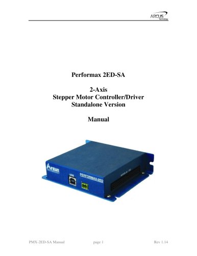 pmx-2ed-sa
78 Pages
 ace-sxe
88 Pages
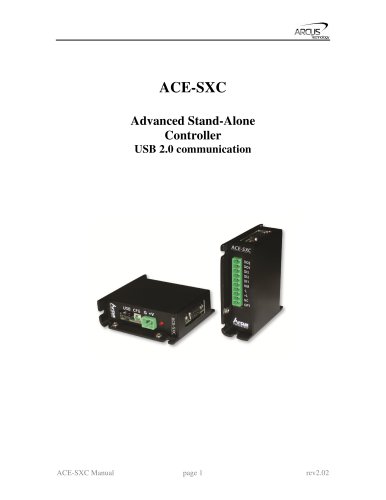 ace-sxc
66 Pages
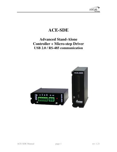 ace-sde
88 Pages
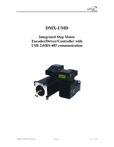 dmx-umd
87 Pages
 dmx-k-drv
32 Pages
 dmx-eth
78 Pages
 dmx-a2-drv
26 Pages
Related Searches
- Electromotor
- DC electromotor
- Multipole motor
- 24 V motor
- 2-pole motor
- Motor controller
- 48 V motor
- Stepper motor controller
- Integrated-drive motor
- Programmable motor controller
- Closed-loop motor controller
- Motor with integrated controller
- Single-axis motor controller
- Development kit
- Microstepping motor controller
- Multi-axis motor controller
- 2-axis motor controller
*Prices are pre-tax. They exclude delivery charges and customs duties and do not include additional charges for installation or activation options. Prices are indicative only and may vary by country, with changes to the cost of raw materials and exchange rates.
About DirectIndustry
DirectIndustry is a marketplace that offers B2B players a complete experience, from product sourcing to purchase. DirectIndustry is an entity of VirtualExpo Group.
Are you a buyer?
Are you a supplier?