- Catalogs
- Applied Power Systems, Inc
- BAP-1551 Half Bridge IGBT Driver
BAP-1551 Half Bridge IGBT Driver
1 /14Pages

BAP-1551 Half Bridge IGBT Driver
1 /14Pages
Catalog excerpts
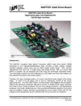
APPLIED POWER SYSTEMS, INC. BAP1551 Gate Drive Board BAP1551 Gate Drive Board Application Note and Datasheet for Half Bridge Inverters Figure 1: BAP1551 IGBT Gate Driver Board Patent Pending Introduction The BAP1551 Insulated Gate Bipolar Transistor (IGBT) Gate Drive Board (GDB) discussed in this Datasheet/Applications Note provides a safe, reliable, isolated interface between control logic and an IGBT based power stage. With minimal development time and cost, a single phase half bridge inverter, with up to three dual IGBTs in parallel, can be designed and built using the techniques described below. Two half bridge inverters can be configured as a full bridge and three half bridges can be combined to create a three phase system. Typically, the most unreliable portion of a motor controller/inverter design is the power stage. In most if not all cases, this is due to inadequate control of the power semiconductors. The APS IGBT GDB is a robust design (see Figure 1 Block diagram) offering the necessary protection features to ensure a reliable power stage including: two forms of over current protection, DC link over voltage protection, over temperature protection, and under voltage lock-out. Also provided as feedback signals to the control logic are isolated, analog, real-time representations of the output current, the DC link voltage and the temperature sensor interface that can be mounted on a heatsink. Fax: 516.935.2603 Website: www.appliedps.com Page 1 of 14 Rev.: 081230
Open the catalog to page 1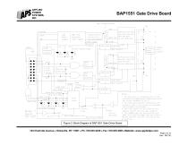
APPLIED POWER SYSTEMS, INC. BAP1551 Gate Drive Board 1, The board nay be configured with a 14 pin connector, providing either Temperature or DC Bus voltage feedback at pin 12, 2, The gate drive isolation transformers are tested to 2500 V from primary to secondary and secondary to secondary, 3, The fault signals to the connector are logically correct, but are open collector. 4, The INHIBIT signal will prevent PVM+ and PVM- from firing the IGBTs until the fault is cleared and PWM+ and PVM- are held low for at least 8uS. 124 Charlotte Avenue • Hicksville, NY 11801 • Ph: 516.935.2230 • Fax: 516.935.2603...
Open the catalog to page 2
BAP1551 Gate Drive Board Circuit Description GDB Power Supply The BAP1551 GDB requires either an unregulated 24 volt (20-30) or regulated 15 volt (14.5-15.5) power supply to operate (see Table 1 for pin assignments). The system designer must choose one supply or the other, whichever is available or preferred. Note: Connecting both power supplies simultaneously will create contention issues that may result in damage to the board. The input voltage is used to generate the logic control power supplies and the isolated bipolar power supplies for the upper and lower IGBTs. The power consumed by the...
Open the catalog to page 3
BAP1551 Gate Drive Board Ohm gate resistors standard, which allows for up to 3 Amp peak current pulse. This resistor is selected to optimize the performance of an IGBT with a gate charge of approximately 1000r|C; however, it will work in many applications. Consult the factory for alternate gate resistor values. The isolated gate drive power supplies are generated with a high frequency transformer. This transformer is high potential tested to 2500 volts between each of its three windings. The primary of the transformer is referenced to the ground of the 24 volt or 15 volt power supply. Each secondary...
Open the catalog to page 4
BAP1551 Gate Drive Board temperature threshold is set on the GDB at 98 ± 2°C, which corresponds to 8.17 volts at pin 12. The threshold can be adjusted for a specific application. Protection Features The APS GDB is equipped with several protection features that will prevent catastrophic system failures. If any of the faults discussed below occur, all gate drive signals are latched off (user provided control signals are inhibited from reaching the gates) and the LED associated with the fault will light. The GDB will remain in a latched off state until both PWM+ and PWM- are held low for at least...
Open the catalog to page 5
BAP1551 Gate Drive Board Over Voltage Protection The over voltage protection senses the DC link input and compares it to a predetermined threshold, 910 volts using 1200 volt devices and 450 volts using 600 volt Devices. When the threshold is exceeded for more than ImS, the gate pulses are latched off 2(is later, and the over voltage LED is illuminated. The gate signals remain latched off until the fault condition is removed and all user provided control signals are held low for at least 8(is. Over Temperature Protection The over temperature protection uses the temperature sense input and compares...
Open the catalog to page 6
BAP1551 Gate Drive Board DC Link Connection - The DC link monitoring and over voltage protection are made possible by the DC link connection, which should be a single 22 AWG wire with a lug on the end to connect to the positive of the DC link. This wire’s interface with the GDB should be the same strain relief technique detailed in the gate lead section above. Standard DC link lead length supplied is 3”. Longer or shorter leads are available upon request. Please see the form at the end of this Datasheet/Applications Note for additional information. Current Sense Connection - When connected to...
Open the catalog to page 7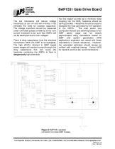
BAP1551 Gate Drive Board The low inductance will reduce voltage overshoots at turn off and will minimize if not eliminate the need for snubber capacitors. The voltage overshoot should be measured under controlled pulsed conditions at the over current threshold to be sure that IGBTs will not be destroyed due to over voltages. There is stray capacitance from the electrical connections within the IGBT to its baseplate. The high dV/dTs inherent in IGBT based power stages will conduct current through this stray capacitance that can cause the heatsinks containing the IGBTs to float to dangerously high...
Open the catalog to page 8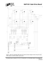
APPLIED POWER SYSTEMS, INC. BAP1551 Gate Drive Board OVERTEMP PHASE OC OVERVOLT UVLO Figure 5: BAP1551 Half-Bridge IGBT Gate Driver board connection diagram shown driving three dual IGBT modules in parallel for higher output current. 124 Charlotte Avenue Fax: 516.935.2603 Website: www.appliedps.com Page 9 of 14 Rev.: 081230
Open the catalog to page 9All Applied Power Systems, Inc catalogs and technical brochures
 BAP-1294 Interface Board
2 Pages
 BAP-1491 Full-Bridge IGBT Driver
12 Pages
 APS BROCHURE
4 Pages


- Bourn And Koch DC power supply
- Bourn And Koch AC/DC power supply
- Bourn And Koch switching power supply
- Bourn And Koch compact power supply
- Multiple-output power supply
- Diode
- DC/DC power supply
- High-performance power supply
- Bourn And Koch three-phase power supply
- Communication interface card
- Open frame power supply
- Current rectifier
- Heatsink
- Analog power supply
- Diode rectifier bridge
- Converter module
- Liquid-cooled power supply
- Inverter power supply