- Catalogs
- Applied Power Systems, Inc
- BAP-1491 Full-Bridge IGBT Driver
BAP-1491 Full-Bridge IGBT Driver
1 /12Pages

BAP-1491 Full-Bridge IGBT Driver
1 /12Pages
Catalog excerpts

APPLIED POWER SYSTEMS, INC. BAP1491 IGBT Gate Drive Board BAP1491 IGBT Gate Drive Board for Three Phase and Full Bridge Inverters Complete IGBT Gate Drive Board with the following feature: Current sensing and heatsink temperature sensing capability Over voltage protection Includes all power supplies DC link voltage sensing Over current protection Single 26 pin header for all I/O and input power Under voltage lock-out Diagnostic LEDs Automatic dead time generation Shoot through protection Introduction The BAP1491 Insulated Gate Bipolar Transistor (IGBT) Gate Drive Board (GDB) discussed in this Datasheet/Application Note provides a safe, reliable, isolated interface between control logic and an IGBT based power stage. With minimal development time and cost, an effective inverter can be designed and built using the techniques described below. Typically, the most unreliable portion of an inverter design is the power stage. In most if not all cases, this is due to inadequate control of the power semiconductors. The APS IGBT GDB is a robust design (see Figure 1 Block diagram) offering the necessary protection features to ensure a reliable power stage including: two forms of over current protection, DC link over voltage protection, over temperature protection, and under voltage lockout. Also provided as feedback signals to the control logic are isolated, analog, real-time representations of each phase output current, the DC link voltage and a temperature sensor interface that can be mounted on a heatsink.
Open the catalog to page 1
BAP1491 IGBT Gate Drive Board 124 Charlotte Avenue • Hicksville, NY 11801 • Ph: 516.935.2230 • Fax: 516.935.2603 • Web: www.appliedps.com Page 2 of 12 Rev. 082208
Open the catalog to page 2
BAP1491 IGBT Gate Drive Board Circuit Description GDB Power Supply The BAP1491 Gate Drive Board requires either an unregulated 24 (20-30) volt or regulated 15 (14.515.5) volt power supply to operate (see Table 1 for pin assignments). The system designer must choose one supply or the other, whichever is available or preferred. Note: Connecting both power supplies simultaneously will create contention issues that may result in damage to the board. The input voltage is used to generate the logic control power supplies and the required isolated bipolar power supplies for each individual IGBT. The...
Open the catalog to page 3
BAP1491 IGBT Gate Drive Board Gate Drive Signals After the control signals are integrated with dead time, they are optically isolated and buffered by a transistor stage with the capability to source the high peak currents necessary to turn large IGBTs on and off quickly. The GDB is equipped with 4.3-Ohm gate resistors standard that allow up to a 3 Amp peak current pulse. This resistor is selected to optimize the performance of an IGBT with a gate charge of approximately 1000r|C; however, it will work in many applications. Consult factory for alternate gate resistor values. The isolated gate drive...
Open the catalog to page 4
BAP1491 IGBT Gate Drive Board signals are held low for at least 8ps. When both control signals are held low for a minimum of 8ps, the latched fault will be reset. If the cause of the fault condition is removed, the control signals will be applied to the gates and the LED will be extinguished. Reset Function This 8Ls reset feature is the reason that user generated dead time is neither required nor desired. If dead time of 8Ls is supplied with the control signals, the unit will not properly latch off on fault event and will continue to fire during fault conditions. If an over current fault exists,...
Open the catalog to page 5
BAP1491 IGBT Gate Drive Board APPLIED POWER SYSTEMS, INC. Connecting the APS GDB to a Three Phase System In order for the APS GDB to interface with a power stage, several connections need to be addressed: Ribbon Cable connector J1 - A 26 pin ribbon cable connector (3M part #3399-7600 with strain relief part #3448-3026 or an equivalent) is required to interface the GDB with the customer provided controls. Pin assignments are detailed in Table 1. If the control logic already exists without a 26-pin header, terminal block to 26-pin header adapters are available. Gate Leads - The power stage should...
Open the catalog to page 6
BAP1491 IGBT Gate Drive Board LEM PhC Current Connector Current Connector Current Connector 124 Charlotte Avenue • Hicksville, NY 11801 • Ph: 516.935.2230 • Fax: 516.935.2603 • Web: www.appliedps.com Page 7 of 12 Rev. 082208
Open the catalog to page 7
BAP1491 IGBT Gate Drive Board System Considerations There are many issues to consider when packaging a power stage including capacitor selection and configuration, routing of high current connections, heat sink size, and air or liquid cooling. These issues should be considered at the design stage and if not adequately addressed, a reliable power stage may never be realized. Capacitors should be selected with ripple current capabilities sufficient for the particular application. For safety purposes, permanent bleeder resistors should be installed across the capacitors to ensure they are discharged...
Open the catalog to page 8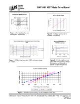
BAP1491 IGBT Gate Drive Board Power Consumption vs. Switching Freq for Three Phase GDB Figure 7: GDB driving three dual IGBTs with gate charge of 1100|jC. 124 Charlotte Avenue • Hicksville, NY 11801 • Ph: 516.935.2230 • Fax: 516.935.2603 • Web: www.appliedps.com Page 9 of 12 Rev. 082208
Open the catalog to page 9
APPLIED POWER SYSTEMS, INC. BAP1491 IGBT Gate Drive Board ji5 There are three “headers” available on the board to interface with three separate Hall effect sensors (LEMs). Headers are not installed on the board to allow for the strain relief hook-up detailed in Figure 3. However, the pads are separated by standard .100 spacing to allow for the installation of headers with .100 spacing. Note: The wiring for the B and C connectors is 1 to 1, i.e. pin 1 on the GDB goes to pin 1 on the LEM, pin 2 goes to pin 2, pin 3 to pin 3, and pin 4 to pin 4. Pin 2 and pin 3 are reversed at the GDB for the phase...
Open the catalog to page 10
APPLIED POWER SYSTEMS, INC. BAP1491 IGBT Gate Drive Board ABSOLUTE MAXIMUM RATINGS (Voltages referenced to GND of GDB Power Supply) NOTE: The AP-1491 can be modified to accept TTL level PWM control signals. See Fax form at the end of this Datasheet/Application Note.
Open the catalog to page 11All Applied Power Systems, Inc catalogs and technical brochures
 BAP-1294 Interface Board
2 Pages
 BAP-1551 Half Bridge IGBT Driver
14 Pages
 APS BROCHURE
4 Pages


- DC power supply
- AC/DC power supply
- Switching power supply
- Compact power supply
- Multiple-output power supply
- Diode
- DC/DC power supply
- High-performance power supply
- Three-phase power supply
- Communication interface card
- Open frame power supply
- Current rectifier
- Analog power supply
- Diode rectifier bridge
- Converter module
- Gate driver
- Liquid-cooled power supply
- Inverter power supply