
- Catalogs
- APM Automation Solutions Ltd.
- 3DLevelManager


3DLevelManager

3DLevelManager
This manual provides detailed instructions for the installation, configuration, and operation of the 3DLevelManager software, intended for trained personnel. It includes safety guidelines and symbols indicating important information and warnings.
The 3DLevelManager software is used for configuring and monitoring 3DLevelScanner devices. It supports various communication interfaces and offers features like wizard-based configuration, logging options, and advanced analysis tools. Compatibility with specific software and firmware versions and certain system specifications are required.
The installation involves inserting the software CD, running the setup wizard, and following prompts to complete the installation. Users can choose installation preferences such as the installation folder and user access levels.
The software is designed for both end users and technical personnel, offering different modes of operation such as Standard, Technician, and Senior Technician modes, each with varying levels of access and functionality. Connection status and device information are displayed on the interface, and measured parameters like volume, level, and temperature are monitored.
The software supports multiple connection options including RS-485, HART, GSM, GPRS, and TCP/IP. RS-485 is recommended for faster communication. The connection process involves selecting the communication interface and establishing a data connection between the software and the scanner.
For RS-485 connections, a 250 Ohm resistor is necessary when using an RS-232/USB HART Modem. The setup involves a PC running 3DLevelManager software connected to a 3DLevelScanner via a HART modem.
The GSM option facilitates modem-to-modem communication, requiring a GSM modem on both the scanner and computer sides. The GPRS option allows IP connection to a remote 3DLinkPro, necessitating a TCP port to be opened and forwarded. An SMS message must be sent in a specific format to establish the connection.
TCP/IP connections convert RS-485 data for transfer over TCP/IP. GPRS + SMS options automate SMS sending for connection establishment, requiring a 3DLinkPro unit.
In a Daisy-Chain setup, multiple scanners can be connected, with each assigned a unique polling address.
The 3DLevelManager stores connection details in a PhoneBook.ini file, allowing for easy management and retrieval of connection settings.
A 5-stage configuration wizard guides the initial setup of the 3DLevelScanner, including system parameters, vessel parameters, device position, filling points, and calibration levels. Each step involves specific settings such as measurement units, vessel geometry, and calibration levels.
Post-configuration, advanced parameters like Material Slope and Damping Time can be adjusted. Grades Analysis and False Echo Mapping are crucial for accurate measurements, especially in complex vessel environments.
The software logs all data from the scanner, viewable through the Log Viewer. A 3D Image Profile feature provides a graphical representation of the material surface.
The software includes various menus for file management, communication setup, and connection management. The File menu allows parameter loading and saving, while the Communications menu facilitates device connection and communication quality testing.
- TCP/IP: Connects via a TCP/IP network to an RS-485 connection. Requires setting the server IP, IP port, and chain number for 3DMultiVision Server connections.
- HART: Utilizes a HART modem, requiring selection of the serial COM port and scanner polling address.
- GSM (Modem): Involves a local GSM modem, needing the serial COM port, site name, and phone number.
- GPRS: Connects through the internet using 3DLinkPro, requiring local IP port and polling address.
- GPRS + SMS: Uses SMS messages via a GSM modem, needing site name, COM port, polling address, and IP settings.
- GPRS + SMS Server: Available in Senior Technician mode, involves similar settings as GPRS + SMS with additional TCP port configuration.
Essential for daisy-chain connections, with an address range of 00 to 63 or multiple. Each scanner must have a unique address.
Tests connection quality, checking for packet errors and delays. A good result shows low delay and no errors.
Logs data for technical support, available in HTML format.
- Configuration Wizard: Guides initial setup and configuration.
- Advanced Parameters: Available in Technician mode, allows adjustment of algorithm parameters like Output Damping Time, Material Slope, and Capacity settings.
- Advanced Parameters for Senior Technician: Includes beam activation settings and range limitations.
Controls the 4-20mA output signal, allowing simulation for synchronization with PLCs.
The document describes the output settings for a device that can send a standard 4-20mA signal, a reverse 20-4mA signal, or a fixed value. The output type can be set to Average, Min Level, or Max Level.
Users can define how the 4-20mA output behaves, selecting between Volume, Mass, Level, or Distance. Volume calculations can be based on silo structure or linearization tables. Mass calculations can use fixed or variable bulk density values.
The document details various software menu options, including device menu operations like uploading and downloading settings, resetting devices, and viewing 3D images. The View Menu allows for 3D visual mapping and log viewing, while the Tools Menu includes analysis tools for signal types and false echo mapping.
Users can generate 3D graphical representations of scanned data, with options to rotate, zoom, and pan the images. Additional features include showing vessel geometry, fill points, and axes, as well as saving images.
The document explains how to manage logs, including viewing measurement logs, historic logs, and performing grades analysis. Logs can be displayed in various units and formats, and users can zoom, pan, and merge log files.
The document provides guidance on performing grades analysis and mapping false echoes, including manual and automatic mapping options. It suggests taking manual measurements for reference during analysis.
The document outlines the process of identifying and mapping false echoes in the Grades Analysis of a 3DLevelScanner. It involves zooming into the area of false echoes, manually scanning the range, and setting a threshold level to map out these echoes. The process is crucial for accurate measurements and involves using the False Echo Mapping function under the Tools menu.
The document provides instructions for updating the firmware of the 3DLevelScanner. It includes selecting the appropriate firmware file, starting the update, and resetting the device to factory settings if necessary. It warns against downgrading firmware versions due to potential issues.
Instructions are given for upgrading or downgrading between different models of the scanner. A password is required for upgrading to higher models, which can be obtained from a distributor or APM headquarters.
The document describes different operating modes of the scanner, including Standard, Technician, Senior Technician, and Debug modes, each requiring specific passwords for access.
The Help menu provides access to the operation manual and version details of the software.
The agreement outlines the terms of use for the software and hardware, including license restrictions, ownership rights, and use restrictions. It emphasizes the importance of compliance with ATEX standards for certain products to prevent damage or injury.
Catalog excerpts
Devic* Into from level to volume Configuration & Monitoring
Open the catalog to page 1
3DLevelManager Operating Instructions © 2013 APM all rights reserved
Open the catalog to page 2
About this Document This manual provides detailed product related information, installation, configuration and operation instructions for 3DLevelManager software. The manual is designed for trained personnel. Please read it entirely and carefully before proceeding with installation of the product. The following symbols indicate different sections of additional information as follows: IMPORTANT: An indication for additional information, tips, hints or an indication of helpful additional knowledge. WARNING: Indication of a potentially dangerous situation, which could result in serious injury to...
Open the catalog to page 3
The 3DLevelManager™ software is a configuration and monitoring tool for managing 3DLevelScanner™ devices. The software supports various methods for connecting to the scanners, monitoring their measurement readings, configuring their various parameters, log results and generating various types of graphical reports. This manual is compatible with SW version 3.5.0 and FW version 4.0.137 and above. Major features of the 3DLevelManager software: Supports HART, RS-485/Multi-drop, GSM, GPRS and TCP/IP communication interfaces to the linked scanners Supports all 3DLevelScanner models (S, M, MV, ML and...
Open the catalog to page 4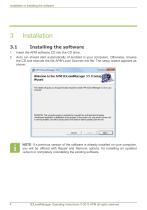
Installation ● Installing the software Insert the APM software CD into the CD drive. Auto run should start automatically (if enabled in your computer). Otherwise, browse the CD and execute the file APM Level Scanner.msi file. The setup wizard appears as shown: NOTE: If a previous version of the software is already installed on your computer, you will be offered with Repair and Remove options, for installing an updated version or completely uninstalling the existing software. 3DLevelManager Operating Instructions © 2013 APM all rights reserved
Open the catalog to page 5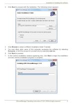
Installation ● Installing the software Click Next to proceed with the installation. The following screen appears: Click Browse to select a different installation folder if needed. You may allow other users of this computer accessing the software by selecting Everyone, or limit the access for yourself only by selecting Just me. Click Next to proceed. In the Confirm Installation window appearing next, click Next to begin the installation and wait until the installation progress is complete: 3DLevelManager Operating Instructions © 2013 APM all rights reserved
Open the catalog to page 6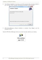
Installation ● Installing the software The software installation is in process, and all the necessary files are being installed in your computer. When complete, the following confirmation screen appears: APM 3DLevelManager software installation is complete. Press Close to exit the installation wizard. Note the APM 3DLevelManager shortcut icon which has been added to your desktop. 3DLevelManager Operating Instructions © 2013 APM all rights reserved
Open the catalog to page 7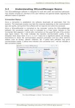
Installation ● Understanding 3DLevelManager Basics The 3DLevelManager software is designed for both end users and technical personnel. This chapter includes an overview of the user interface and general details regarding the different modes of operation. Connection Status Once a connection is established, the software downloads all parameters from the scanner. The download process may take few seconds depending on the communication type and quality, during which the software will not respond and cannot be accessed. Once a 3DLevelScanner is connected to the computer running the 3DLevelManager...
Open the catalog to page 8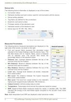
Installation ● Understanding 3DLevelManager Basics Device Info The following device information is displayed on top of the screen: Connection status Hardware interface and port number used for communication with the device Device polling address Tag Name (as defined for this connection) Electronic card serial number Firmware version of the electronic card Hardware version of the electronic card Device type (S / M / MV / ML / MVL) The Device Information area Measured Parameters The following device measured parameters are displayed on the right area of the screen, as shown to the right: First...
Open the catalog to page 9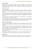
Installation ● Understanding 3DLevelManager Basics Standard Mode Standard Mode is the default operating mode of the software. This mode allows connecting and disconnecting the scanner, viewing of log graphs and 3D image and performing basic grades analysis. Scanner configuration and Advanced Parameters are disabled for this mode. Technician Mode Technician Mode allows configuration of advanced parameters which are not available under Viewer mode (the default operating mode). Switching to Technician mode requires a password. To switch to Technician mode, choose Tools → Operating Mode → Technician...
Open the catalog to page 10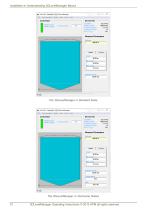
■ile Communication Device View Took Help Device Info Serial Number: Firmware Version : Hardware Version : Device Type : Measured Parameters * S' o APfv - eihnidc- - APM iDLevelK'anagsr Com muni cation Devio View TOOIE. Help Device Info Serial Number: Firmware Version : Hardware Version : Device Type : Measured Parameters Output Current_
Open the catalog to page 11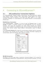
Connecting to 3DLevelScannerTM ● 3DLevelScanner Connection Options Connecting to 3DLevelScannerTM 3DLevelScanner Connection Options The 3DLevelManager Software enables communication with 3DLevelScanner devices using different methods: RS-485, HART, GSM Modem, GPRS Modem and TCP/IP. Communicating using an RS-485 is much faster than GSM, GPRS or via a HART connection, therefore it is recommended to use standard RS-485 as communications infrastructure. Establishing a Connection Press Communication → Connect... (or click the large red Connect button, or press Ctrl+M) to initiate a connection between...
Open the catalog to page 12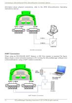
Connecting to 3DLevelScannerTM ● 3DLevelScanner Connection Options information about physical connections, refer to the APM 3DLevelScanner Operating Instructions manual. HART Connection When using an RS-232/USB HART Modem, a 250 Ohm resistor is required.The figure below shows a local connection between a PC running the 3DLevelManager software and a 3DLevelScanner, using a HART modem connection. HART Modem Connection 3DLevelManager Operating Instructions © 2013 APM all rights reserved
Open the catalog to page 13All APM Automation Solutions Ltd. catalogs and technical brochures
 3D MultiVision Software
4 Pages
 Volcan White Paper
5 Pages
 3DLevelScanner HC
4 Pages
 3DLevelScanner HT
4 Pages
 3DLevelScanner S / M / MV
8 Pages


