
- Catalogs
- APLISENS S.A.
- Fuel Level Probe Type CS-27/RS/U

- Company
- Products
- Catalogs
- News & Trends
- Exhibitions
Fuel Level Probe Type CS-27/RS/U
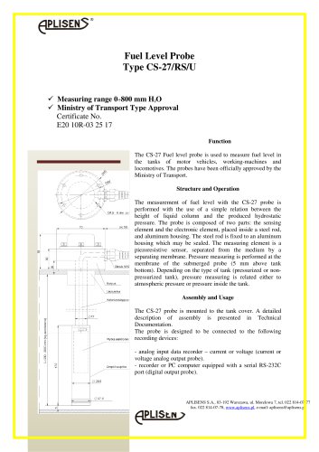
Fuel Level Probe Type CS-27/RS/U
The CS-27 Fuel Level Probe is designed for measuring fuel levels in motor vehicles, working machines, and locomotives. It is officially approved by the Ministry of Transport with Certificate No. E20 10R-03 25 17.
The probe measures fuel levels using the hydrostatic pressure principle, which correlates the height of the liquid column to the pressure produced. It consists of a sensing element and an electronic element housed in a steel rod and aluminum casing.
The probe uses a piezoresistive sensor separated from the medium by a membrane. It measures pressure at the membrane, located 5 mm above the tank bottom. The pressure measurement is adjusted based on whether the tank is pressurized or not.
The probe is mounted on the tank cover and can be connected to analog input data recorders or devices with a serial RS-232C port. Detailed assembly instructions are provided in the technical documentation.
- Measuring range: 0-800 mm H2O (special versions available)
- Pipe length: 800 mm (special versions available)
- Maximum overload: < 100 kPa
- Basic error: < 0.16%
- Hysteresis, replicability: < 0.05%
- Long-term stability: < 0.1% over two years
- Working temperature range: -25 to 80°C
- Compensation temperature range: -25 to 40°C
- Output signal options: 0-10V, 0-5V, 0-4.5V, 0-2.5V, 100-3800 bit
- Power supply: Various options depending on output signal
- Housing protection: IP 68
- Temperature fluctuation error: 0.3% per 10°C
Standard and special versions are available with different measuring ranges, pipe lengths, and output signals. Examples include:
- CS-27/RS/U with 0-800 mm H2O range and 0-10V output
- CS-27/RS-232 with 0-800 mm H2O range and RS-232 output
- CS-27/RS-485 with 0-800 mm H2O range and RS-485 output
Catalog excerpts
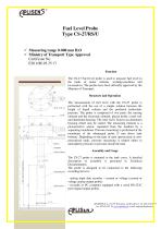
Fuel Level Probe Type CS-27/RS/U Measuring range 0÷800 mm H2O Ministry of Transport Type Approval Certificate No. E20 10R-03 25 17 Function The CS-27 Fuel level probe is used to measure fuel level in the tanks of motor vehicles, working-machines and locomotives. The probes have been officially approved by the Ministry of Transport. Structure and Operation The measurement of fuel level with the CS-27 probe is performed with the use of a simple relation between the height of liquid column and the produced hydrostatic pressure. The probe is composed of two parts: the sensing element and the electronic element, placed inside a steel rod, and aluminum housing. The steel rod is fixed to an aluminum housing which may be sealed. The measuring element is a piezoresistive sensor, separated from the medium by a separating membrane. Pressure measuring is performed at the membrane of the submerged probe (5 mm above tank bottom). Depending on the type of tank (pressurized or nonpressurized tank), pressure measuring is related either to atmospheric pressure or pressure inside the tank. Assembly and Usage The CS-27 probe is mounted to the tank cover. A detailed description of assembly is presented in Technical Documentation. The probe is designed to be connected to the following recording devices: - analog input data recorder – current or voltage (current or voltage analog output probe). - recorder or PC computer equipped with a serial RS-232C port (digital output probe). APLISENS S.A., 03-192 Warszawa, ul. Morelowa 7, tel. 022 814-07-77 fax. 022 814-07-78, www.aplisens.pl, e-mail: [email protected]
Open the catalog to page 1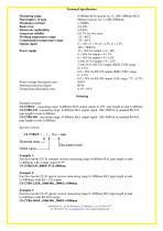
Technical Specification Measuring range Pipe length L in tank Maximum overload Basic error Hysteresis, replicability Long-term stability Working temperature range Compensation temperature range Output signal Power supply Power voltage fluctuation error Housing protection degree Temperature fluctuation error 0÷800mm H2O (special ver. 0...200÷2000mm H2O) 800mm (special ver. L=200÷2000mm) < 100kPa < 0.16% < 0.05% < 0.1% for two years -25 ÷ 80°C -25 ÷ 40°C 0 ÷ 10V ; 0 ÷ 5V, 0 ÷ 4.5V, 0 ÷ 2.5V 100 ÷ 3800 bit 12 ÷ 36V for output = 0 ÷ 10V 8 ÷ 36V for output = 0 ÷ 5V 8 ÷ 36V for output = 0 ÷ 4.5V 3.3±0,1V...
Open the catalog to page 2All APLISENS S.A. catalogs and technical brochures
 PRODUCT CATALOGUE 2026/2027
188 Pages

Archived catalogs
 2019-2020 PRODUCT CATALOGUE
176 Pages
 Product catalog 2017
166 Pages
 2022-2023 PRODUCT CATALOGUE
180 Pages
 PRODUCT OVERVIEW
6 Pages
 PRODUCT CATALOGUE 2016/2017
168 Pages
 APLISENS CATALOGUE 2015/2016
156 Pages
 Level transmitters
12 Pages
 APC-2000ALW
5 Pages


- Valve
- Manual valve
- Stainless valve
- Flowmeter
- DC power supply
- Ball valve
- AC/DC power supply
- Temperature probe
- Volume flow monitor
- Liquid flow monitor
- Measuring device
- APLISENS data-logger
- Resistance temperature sensor
- Lever valve
- APLISENS pressure transmitter
- Pressure gauge
- Level limit switch
- Calibration system
- APLISENS analog pressure transmitter