CA Series
1 /4Pages

CA Series
1 /4Pages
Catalog excerpts
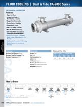
COPPER & STEEL CONSTRUOTiON Features ■ Super High Flow ■ Largest Flow Rates & Heat Transfer Available ■ rugged Steel Construction ■ Custom Designs Available ■ Competitively priced ■ 3/8" & 5/8" tubes Available ■ Max. 10" Diameter, 12' Long ■ 150# ANSi/ASME Flanged Shell Connections (Metric Available) ■ Optional Construction on CA-2000 Series: Tubes, Tubesheets, and End Bonnets ■ End Bonnets Removable For Servicing ■ Saddle Brackets For Incremental Mounting Ratings Maximum Shell Pressure 150 psi Maximum Tube Side Pressure 150 psi Maximum Temperature 300° F How to Order Materials Headers Steel Shell Steel Shell Connections Steel Baffles Brass End Bonnets Cast Iron Mounting Brackets Steel/Cast Iron Gaskets Nitrile Rubber/Cellulose Fiber Nameplate Aluminum Foil Model Model Size Selected Baffle Series Spacing Tubeside Passes 0 - One Pass T - Two Pass F - Four Pass Maximum Flow Rates Baffle Baffle CA = NPT tubeside bottom connections; ASME/ANSI flange shell top connections. CAM = BSPP shellside connections; BSPP tubeside connections. Cooling Tube Material Blank - Copper CN - CuNi SS - Stainless Steel AD - Admiralty Brass End Bonnet Material Blank - Cast Iron NP - Electroless Nickel Plate Tubesheet Material Blank - Cast Iron W - CuNi S - Stainless Steel Zinc Anodes Blank - None Z - Zinc
Open the catalog to page 1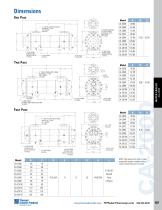
Thermal Transfer Products NOTE: We reserve the right to make reasonable design changes without notice. Dimensions are in inches.
Open the catalog to page 2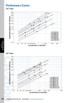
Performance Curves HORSEPOWER REMOVED @ 40°F APPROACH HORSEPOWER REMOVED @ 40°F APPROACH
Open the catalog to page 3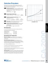
Selection Procedure Performance Curves are based on 100SSU oil leaving the cooler 40°F higher than the incoming water temperature (40°F approach temperature). Curves are based on a 2:1 oil to water ratio. IStep 1 Determine the Heat Load. This will vary with different systems, but typically coolers are sized to remove 25 to 50% of the input nameplate horsepower. (Example: 100 HP Power Unit x .33 = 33 HP Heat load.) If BTU/Hr. is known: HP = 2545 IStep 2 Determine Approach Temperature. Desired oil leaving cooler °F - Water Inlet temp. °F = . Actual , Approach |Step 3 | Determine Curve Horsepower...
Open the catalog to page 4All API Schmidt-Bretten, API Heat Transfer group catalogs and technical brochures
 SCHMIDT EVAPORATORS
10 Pages
 OCA Series
6 Pages
 SIGMASTAR
2 Pages
 Basco® Type 500
1 Page
 SCHMIDT® SIGMASHELL
8 Pages
 BOL Series
8 Pages
 PCR With FinSep®
1 Page
 Gland steam condenser
1 Page
 Hairpin heat exchangers
1 Page
 SIGMA Plate Heat Exchangers
10 Pages
 AOC Series
4 Pages
 AOL Series
4 Pages
 BOL Series
6 Pages
 TTP Engine Cooling
8 Pages
 Evaporators
8 Pages
 SIGMASHELL
1 Page
 Basco Pipeline Aftercooler
8 Pages
 Basco Type OP
8 Pages
 Basco U-Tube
8 Pages
 Basco/Whitlock Hub Design
16 Pages
 Basco Type 500
12 Pages


Archived catalogs
 AOC DC Fan Drive
4 Pages
 OCA Series
28 Pages
 MA Series
4 Pages
 DH Series
4 Pages
 UC Series
5 Pages
 EC Series
6 Pages
 EK Series
8 Pages
 BP Series
20 Pages
 BPS Series
4 Pages
 BPCH Series
2 Pages
 EKT Series
2 Pages


- Bourn And Koch piping
- Semi-rigid tube
- Bourn And Koch liquid cooler
- Bourn And Koch heat exchanger
- Bourn And Koch smooth piping
- Bourn And Koch liquid/liquid heat exchanger
- Bourn And Koch air cooler
- Bourn And Koch water cooler
- Bourn And Koch industrial cooler
- Compact recirculation chiller
- Bourn And Koch tubular heat exchanger
- Bourn And Koch plate heat exchanger
- Bourn And Koch stainless steel heat exchanger
- Air-cooled blast chiller
- Bourn And Koch stainless steel cooler
- Bourn And Koch gas/liquid heat exchanger
- Bourn And Koch industrial heat exchanger
- Pasteurizer
- Bourn And Koch compact heat exchanger