SWR200
1 /11Pages

SWR200
1 /11Pages
Catalog excerpts

SWR200 Precision Sine Wave Reference FEATURES • • • • • • Very High Accuracy: +7.071 Vrms ±0.5% Extremely Low Drift: 20 ppm/°C (-55°C to +125°C) Excellent Stability: 10 ppm/1000 Hrs. Typical Low Distortion: 0.1% THD @ F = 3300 Hz Hermetic 14-pin Ceramic DIP Military Processing Option Transducer Excitation High Resolution Servo Systems High Precision Test and Measurement Instruments AC Voltage Standard LVDT or RVDT Reference Multiplying D/A Reference DESCRIPTION SWR200 is a Precision Sine Wave Reference providing an ultra stable sine wave output of +7.071 V at ±0.5% initial accuracy and temperature coefficient as low as 20 ppm/°C over the full military temperature range. The extreme accuracy is made possible by a chopper-based AGC circuit. The temperature characteristic of the chopper circuit compensates the typical nonlinearity of the internal DC zener reference, resulting in a nearly linear amplitude-temperature characteristic. Frequency of the SWR200 is programmable with two external capacitors. The SWR200 is available in a 14-pin bottom braze package. They are hermetically sealed and “M” versions are screened for high reliability and quality. SWR200 is well suited for any application requiring a stable sine wave source. The SWR200 can be used as a reference source in precision sensing systems based on LVDT or RVDT position sensors. A programmable AC reference can be constructed using the SWR200 as a reference for a high accuracy multiplying Digital to Analog Converter. SELECTION GUIDE Output (TYP) Temperature Operating Range © Apex Microtechnology Inc. All righ
Open the catalog to page 1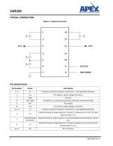
TYPICAL CONNECTION Figure 1: Typical Connection
Open the catalog to page 2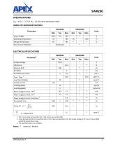
SWR200 SPECIFICATIONS VPS = ±15 V, T = 25°C, RL = 10 kΩ unless otherwise noted. ABSOLUTE MAXIMUM RATINGS Parameter Power Supply Operating Temperature Storage Temperature Short Circuit Protection Output Voltage Initial Error Warmup Drift Output Current Long-Term Stability DC Offset Over Temp. Line Regulation Load Regulation Power Supply Current, +PS 3 Power Supply Current, -PS 3 Power Supply Current, Distortion 3 Normalized Error 1. Pin 8 is internally connected to Pin 7 and can be used as Ref. GND. 2. Using the Box Method, the specified value is the maximum deviation from the output voltage at...
Open the catalog to page 3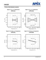
TYPICAL PERFORMANCE GRAPHS Figure 2: VOUT vs. Temperature Figure 3: VOUTvs. Temperature Upper Limit Lower Limit
Open the catalog to page 4
Figure 6: Distortion vs. Temperature Figure 8: Normalized Distortion vs. Figure 7: Distortion vs. Frequency Figure 9: Power Supply Current vs.
Open the catalog to page 5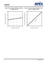
Figure 10: Case Temp. Rise Above Ambient Figure 11: Junction Temp. Rise Above Case vs. Output Current Temp. vs. Output Current
Open the catalog to page 6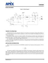
BLOCK DIAGRAM Figure 12: Block Diagram The following refers to the schematic in Figure 12. Al and A2 are connected as a phase-shift oscillator cir- cuit with the frequency set by the external capacitors CI and C2. Q4 is included in the feedback loop of Al as a gain control element. The oscillator output is fed to the chopper amplifier which develops an absolute value representation of the oscillator output. The chopper output is compared to a precision DC reference in integrator amplifier A3. This DC error signal is used to control the gain setting FET Q.4. As in all precision zener based DC...
Open the catalog to page 7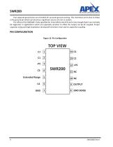
Two separate ground pins are provided for accurate ground sensing. This minimizes errors due to drops in the ground pin which can become a significant source of error in sockets. The offset of the SWR200 is fully specified for initial offset and drift and is low enough that it can normally be neglected. In applications which are especially sensitive to offset the output can be AC coupled. Proper capacitor sizing and high impedance sensing will minimize errors due to capacitive coupling. Extended Range
Open the catalog to page 8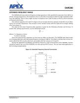
SWR200 EXTENDED FREQUENCY RANGE The SWR200 with two external frequency setting capacitors is fully specified for operation from 400 Hz to 10 kHz. At lower frequencies, the limitations occurs in the AGC circuit that provides the high amplitude stability of the SWR200. There is also a slight increase in distortion from 1500 Hz down to 400 Hz, which continues as frequency decreases. Two external capacitors (C3 and C4 in figure 14) can increase the time constant of the AGC circuit allowing for use at lower frequencies. This increase in time constant comes with the trade-off of a longer settling time...
Open the catalog to page 9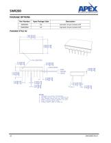
PACKAGE OPTIONS 1. Dimensions are inches & [millimeters]. 2. Bracketed alternate units are for reference only. 3. Pins: Phosphor bronze, Gold over Nickel plated. 4. Material: Alumina Ceramic substrate and cover. 5. Cover: Electroless Nickel plated.
Open the catalog to page 10
NEED TECHNICAL HELP? CONTACT APEX SUPPORT! For all Apex Microtechnology product questions and inquiries, call toll free 800-546-2739 in North America. For inquiries via email, please contact [email protected]. International customers can also request support by contacting their local Apex Microtechnology Sales Representative. To find the one nearest to you, go to www.apexanalog.com IMPORTANT NOTICE Apex Microtechnology, Inc. has made every effort to insure the accuracy of the content contained in this document. However, the information is subject to change without notice and is provided...
Open the catalog to page 11All Apex Precision Product catalogs and technical brochures


Archived catalogs
 2008 Apex Product Summary
8 Pages
 2009 Cirrus Logic Product Summary
36 Pages
 Mixed-Signal Audio Brochure
64 Pages


- Signal amplifying integrated circuit
- Power amplifying integrated circuit
- Measuring amplifier
- Voltage amplifier
- DC amplifier
- Electronic amplifier
- High-voltage amplifier
- Low-noise amplifier
- Analog amplifier
- Current amplifier
- Adjustable amplifier
- Current output amplifier
- Switching amplifier
- Programmable amplifier
- High-power amplifier
- Operational amplifier
- 2-channel amplifier
- Linear amplifier
- Temperature amplifier
- Differential amplifier