- Catalogs
- Apex Precision Product
- Low Bias, 5A, 100V Power Amplifier
Low Bias, 5A, 100V Power Amplifier
1 /5Pages

Low Bias, 5A, 100V Power Amplifier
1 /5Pages
Catalog excerpts
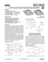
FET Input Power Operational Amplifier FEATURES • LOW BIAS CURRENT — FET Input • PROTECTED OUTPUT STAGE — Thermal Shutoff • EXCELLENT LINEARITY — Class A/B Output • WIDE SUPPLY RANGE — ±12V TO ±50V • HIGH OUTPUT CURRENT — ±5A Peak APPLICATIONS • MOTOR, VALVE AND ACTUATOR CONTROL • MAGNETIC DEFLECTION CIRCUITS UP TO 4A • POWER TRANSDUCERS UP TO 100kHz • TEMPERATURE CONTROL UP TO 180W • PROGRAMMABLE POWER SUPPLIES UP TO 90V • AUDIO AMPLIFIERS UP TO 60W RMS The PA07 is a high voltage, high output current operational amplifier designed to drive resistive, inductive and capacitive loads. For optimum linearity, especially at low levels, the output stage is biased for class A/B operation using a thermistor compensated base-emitter voltage multiplier circuit. A thermal shutoff circuit protects against overheating and minimizes heatsink requirements for abnormal operating conditions. The safe operating area (SOA) can be observed for all operating conditions by selection of user programmable current limiting resistors. Both amplifiers are internally compensated for all gain settings. For continuous operation under load, a heatsink of proper rating is recommended. This hybrid circuit utilizes thick film (cermet) resistors, ceramic capacitors and semiconductor chips to maximize reliability, minimize size and give top performance. Ultrasonically bonded aluminum wires provide reliable interconnections at all operating temperatures. The 8-pin TO-3 package is hermetically sealed and electrically isolated. The use of compressible washers and/or improper mounting torque will void the product warranty. Please see “General Operating Considerations” . Negates optoelectronic instabilities Lead network minimizes overshoot SEQUENTIAL POSITION CONTROL Position is sensed by the differentially connected photo diodes, a method that negates the time and temperature variations of the optical components. Off center positions produce an error current which is integrated by the op amp circuit, driving the system back to center position. A momentary switch contact forces the system out of lock and then the integrating capacitor holds drive level while both diodes are in a dark state. When the next index point arrives, the lead network of C1 and R1 optimize system response by reducing overshoot. The very low bias current of the PA07 augments performance of the integrator circuit. EXTERNAL CONNECTIONS NOTE: Input offset voltage trim optional. RT = 10KΩ MAX Copyright © Apex Microtechnology, Inc. 2012 (All Rights Reserved)
Open the catalog to page 1
PA07 • PA07A ABSOLUTE MAXIMUM RATINGS SUPPLY VOLTAGE, +VS to –VS OUTPUT CURRENT, within SOA POWER DISSIPATION, internal1 INPUT VOLTAGE, differential INPUT VOLTAGE, common mode TEMPERATURE, pin solder - 10s TEMPERATURE, junction1 TEMPERATURE RANGE, storage OPERATING TEMPERATURE RANGE, case SPECIFICATIONS PARAMETER INPUT OFFSET VOLTAGE, initial OFFSET VOLTAGE, vs. temperature OFFSET VOLTAGE, vs. supply OFFSET VOLTAGE, vs. power BIAS CURRENT, initial3 BIAS CURRENT,vs. supply OFFSET CURRENT, initial3 INPUT IMPEDANCE, DC INPUT CAPACITANCE COMMON MODE VOLTAGE RANGE4 COMMON MODE REJECTION, DC TC = 25°C...
Open the catalog to page 2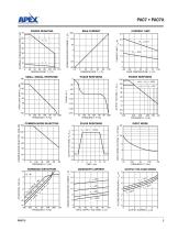
SMALL SIGNAL RESPONSE COMMON MODE REJECTION INPUT NOISE PULSE RESPONSE HARMONIC DISTORTION INPUT NOISE VOLTAGE, VN (nV/√Hz) NORMALIZED QUIESCENT CURRENT, IQ (X) POWER RESPONSE OPEN LOOP GAIN, AOL (dB) COMMON MODE REJECTION, CMR (dB) PHASE RESPONSE CURRENT LIMIT CURRENT LIMIT, ILIM (A) BIAS CURRENT VOLTAGE DROP FROM SUPPLY, VSAT (V) POWER DERATING NORMALIZED BIAS CURRENT, IB (X) INTERNAL POWER DISSIPATION, P (W) OUTPUT VOLTAGE SWING
Open the catalog to page 3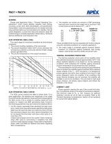
PA07 • PA07A GENERAL Please read Application Note 1 "General Operating Considerations" which covers stability, supplies, heat sinking, mounting, current limit, SOA interpretation, and specification interpretation. Visit www.apexanalog.com for design tools that help automate tasks such as calculations for stability, internal power dissipation, current limit; heat sink selection; Apex Microtechnology’s complete Application Notes library; Technical Seminar Workbook; and Evaluation Kits. SAFE OPERATING AREA (SOA) The output stage of most power amplifiers has three distinct limitations: 1. The current...
Open the catalog to page 4
NEED TECHNICAL HELP? CONTACT APEX SUPPORT! For all Apex Microtechnology product questions and inquiries, call toll free 800-546-2739 in North America. For inquiries via email, please contact [email protected]. International customers can also request support by contacting their local Apex Microtechnology Sales Representative. To find the one nearest to you, go to www.apexanalog.com IMPORTANT NOTICE Apex Microtechnology, Inc. has made every effort to insure the accuracy of the content contained in this document. However, the information is subject to change without notice and is provided...
Open the catalog to page 5All Apex Precision Product catalogs and technical brochures


Archived catalogs
 2008 Apex Product Summary
8 Pages
 2009 Cirrus Logic Product Summary
36 Pages
 Mixed-Signal Audio Brochure
64 Pages


- Liebherr signal amplifier
- Measuring amplifier
- Liebherr voltage amplifier
- DC amplifier
- Electronic amplifier
- High-voltage amplifier
- Low-noise amplifier
- Analog amplifier
- Liebherr current amplifier
- Adjustable amplifier
- Current output amplifier
- Switching amplifier
- Programmable amplifier
- High-power amplifier
- 2-channel amplifier
- Linear amplifier
- Temperature amplifier
- Differential amplifier