- Catalogs
- Apex Precision Product
- 30A, 150V, Power Amplifier with High Internal Power Dissipation
30A, 150V, Power Amplifier with High Internal Power Dissipation
1 /5Pages

30A, 150V, Power Amplifier with High Internal Power Dissipation
1 /5Pages
Catalog excerpts

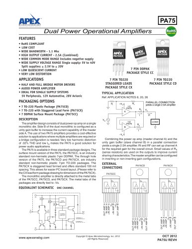
Power Operational Amplifiers FEATURES • MO-127 COPPER POWER DIP™ PACKAGE • HIGH INTERNAL POWER DISSIPATION — 500 watts • HIGH VOLTAGE OPERATION — ±75V • VERY HIGH CURRENT — ±30 amps • INTERNAL SOA PROTECTION • OUTPUT SWINGS CLOSE TO SUPPLY RAILS • EXTERNAL SHUTDOWN CONTROL APPLICATIONS • LINEAR AND ROTARY MOTOR DRIVES • YOKE/MAGNETIC FIELD DEFLECTION • PROGRAMMABLE POWER SUPPLIES to ±68V • TRANSDUCER/AUDIO TO 1000W TYPICAL APPLICATION POSITION FEEDBACK The super power PA03 advances the state of the art in both brute force power and self protection against abnormal operating conditions. Its features start with a copper dip package developed by Apex Microtechnology to extend power capabilities well beyond those attainable with the familiar TO-3 package. The increased pin count of the new package provides additional control features, while the superior thermal conductivity of copper allows substantially higher power ratings. The PA03 incorporates innovative current limiting circuits limiting internal power dissipation to a curve approximating the safe operating area of the power transistors. The internal current limit of 35A is supplemented with thermal sensing which reduces the current limit as the substrate temperature rises. Furthermore, a subcircuit monitors actual junction temperatures and with a response time of less than ten milliseconds reduces the current limit further to keep the junction temperature at 175°C. The PA03 also features a laser trimmed high performance FET input stage providing superior DC accuracies both initially and over the full temperature range. EQUIVALENT SCHEMATIC OBJECT TOOL +5V SHUT DOWN 0/10V DAC R1 DESIRED POSITION The PA03 output power stages contain fast reverse recovery diodes for sustained high energy flyback protection. This hybrid integrated circuit utilizes thick film resistors, ceramic capacitors and silicon semiconductors to maximize reliability, minimize size and give top performance. Ultrasonically bonded aluminum wires provide reliable interconnections at all operating temperatures. The MO-127 Copper, 12-pin Power Dip™ package (see Package Outlines), is hermetically sealed and isolated from the internal circuits. Insulating washers are not recommended. IMPORTANT: Observe mounting precautions. Copyright © Apex Microtechnology, Inc. 2012 (All Rights Reserved)
Open the catalog to page 1
PA03 • PA03A ABSOLUTE MAXIMUM RATINGS SUPPLY VOLTAGE, +VS to –VS OUTPUT CURRENT, within SOA POWER DISSIPATION, internal INPUT VOLTAGE, differential INPUT VOLTAGE, common mode TEMPERATURE, pin solder-10s TEMPERATURE, junction1 TEMPERATURE RANGE, storage OPERATING TEMP. RANGE, case SHUTDOWN VOLTAGE, differential SHUTDOWN VOLTAGE, common mode SPECIFICATIONS PARAMETER INPUT OFFSET VOLTAGE, initial OFFSET VOLTAGE, vs. temperature OFFSET VOLTAGE, vs. supply OFFSET VOLTAGE, vs. power BIAS CURRENT, initial BIAS CURRENT, vs. supply OFFSET CURRENT, initial INPUT IMPEDANCE, DC INPUT CAPACITANCE COMMON MODE...
Open the catalog to page 2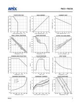
POWER DERATING SMALL SIGNAL RESPONSE COMMON MODE REJECTION HARMONIC DISTORTION QUIESCENT CURRENT INPUT NOISE POWER RESPONSE OUTPUT VOLTAGE SWING PULSE RESPONSE INPUT NOISE VOLTAGE, VN (nV/√Hz) OPEN LOOP GAIN, A (dB) COMMON MODE REJECTION, CMR (dB) PHASE RESPONSE VOLTAGE DROP FROM SUPPLY (V) CURRENT LIMIT CURRENT LIMIT, ILIM (A) BIAS CURRENT NORMALIZED BIAS CURRENT, IB (X) INTERNAL POWER DISSIPATION, P(W)
Open the catalog to page 3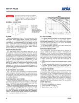
The internal substrate contains beryllia (BeO). Do not break the seal. If accidentally broken, do not crush, machine, or subject to temperatures in excess of 850°C to avoid generating toxic fumes. EXTERNAL CONNECTIONS PHASE COMP. GENERAL Please read Application Note 1 "General Operating Considerations" which covers stability, supplies, heat sinking, mounting, current limit, SOA interpretation, and specification interpretation. Visit www.apexanalog.com for design tools that help automate tasks such as calculations for stability, internal power dissipation, current limit; heat sink selection; Apex...
Open the catalog to page 4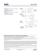
At a gain of 3: 1. Connect a 470pF compensation capacitor between pins 9 and 10. 2. Typical slew rate will be 5V/µs. 3. Typical phase margin will be 45°. At unity gain: 1. Connect a 1.8nF compensation capacitor between pins 9 and 10. 2. Typical slew rate will be 1.8V/µs. 3. Typical phase margin will be 65°. FIGURE 1a. DIRECT DRIVE OF SHUTDOWN Q14 * NOT REQUIRED WHEN USING CMOS LOGIC FIGURE 1b. HIGH VOLTAGE LOGIC INTERFACE FIGURE 1c. THERMALLY ACTIVATED SHUTDOWN ** SELECT SHUTOFF TEMPERATURE SELECT R4 FOR 5V DROP ON R2 R4 30K LOAD THERMAL SENSE TRANSISTOR NEED TECHNICAL HELP? CONTACT APEX SUPPORT!...
Open the catalog to page 5All Apex Precision Product catalogs and technical brochures


Archived catalogs
 2008 Apex Product Summary
8 Pages
 2009 Cirrus Logic Product Summary
36 Pages
 Mixed-Signal Audio Brochure
64 Pages


- Liebherr signal amplifier
- Liebherr power amplifier
- Measuring amplifier
- Liebherr voltage amplifier
- DC amplifier
- Electronic amplifier
- High-voltage amplifier
- Low-noise amplifier
- Analog amplifier
- Liebherr current amplifier
- Adjustable amplifier
- Current output amplifier
- Switching amplifier
- Programmable amplifier
- High-power amplifier
- 2-channel amplifier
- Linear amplifier
- Temperature amplifier
- Differential amplifier