

- Company
- Products
- Catalogs
- News & Trends
- Exhibitions
Camera Adapter

Camera Adapter
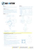
The camera adapter is installed between the scan head's beam entrance and the laser flange using a transition plate (see Fig 1).
Illumination light reflected from the workpiece surface passes through an achromatic F-theta lens, a galvo scanner, a beam splitter, and a CCD lens to reach the CCD sensor. Adjusting the beam splitter compensates for machining and assembly errors, ensuring the laser and reflected light paths are coaxial, aligning the laser processing position with the CCD image detection point.
The FOV is determined by the lens focal length, CCD camera, and the size of the CCD camera's photosensitive element. For a 160mm lens and a CCD target surface size of 6.4mm x 4.8mm, the FOV is 20.4mm x 15.3mm.
- Entering beam
- Beam-entrance side camera adapter
- Camera adapter
- CCD objective
- CCD camera
- Beam-exit side camera adapter
- Scan head
- Exit beam
- Adjust the galvanometer height to find the focus position.
- Mark the crosshair on the processing surface.
- Adjust the focus ring (CW or CCW) until the camera shows a clear image.
- Lock the camera lens.
- Loosen screw 5, adjust the camera orientation to align with the crosshairs, and lock screw 5.
- If the crosshair does not coincide with the CCD image center, adjust knobs 2 and 3 to align them.
- After alignment, replace the protective cover.
- Operating temperature: 25℃ ± 10℃
- Max. Chip size: ½″
- Weight (without camera): ≈2.6Kg
- Laser transmittivity: 95%
Catalog excerpts
Installation (AB-) . The camera adapter is mounted between the scan head's beam entrance and the laser flange (see Fig 1). IftSH Working principle ^fc&, CCD&^£ «CCD^X#o Illumination light reflected from the surface of the workpiece pass through achro matic F-theta, galvo scanner,beam splitter,CCD lens to reach the CCD sensor. Adjust beam splitter position to compensate the error of machinng and assembly to ensure the optical path of the laser and reflected light coxial.Make the laser coi ncides with the CCD image detection point. Other parameters 1 At^X Entering beam 5 CCD^Stt CCD camera 2 Beam-entrance side 6 Beam-exit camera adapter side camera adapter 3 4stt^S^ Camera adapter 7 Scan head 4 CCD^^^^ CCD objective 8 Exit beam ®i?^s FOV CCD&^, CCD^M^xWXX#^^ &160mm^ ^, 135mmCCD^^, CCD^,!XX^1/2"(6.4mm*4.8mm)^M, 20.4mm*15.3mm ($PT^) o Field of view is decided by the lens focal length, CCD camera, CCD camera photosensitive element size together. For example, 160mm lens,CCD camera focus is 135mm, CCD target surface size of 1/2"(6.4mm*4.8mm), the field of view is 20.4mm*15.3mm(see table) Coaxial CCD adapter tuning method and steps Adjust the galvanometer height, find the galvanometer focus position. 2, sa#«i>x®fra+^So Mark the crosshair. 3, £CCD£MMIo Adjust the focus ring 4 (CW or CCW), to the camera showing a clear image. 4, Locking camera. 5, »«5, */«#■««, ^CCD®|^X^ + «Xft-^o Loosen screw 5, CW or CCW adjusting camera, to make the orientation of the image the same as the crosshairs. 6, «^M5o Lock screw 5. ^^2, 3S^^^^ + ^^^CCD@|+^t'^'^S^o Observe the CCD image crosshair and the marked crosshair position. If the two crosshair does not coincide with each other need to open the protective cover, tuning the knob 2 and knob 3. Take © (see Figure 3) as an example, When the knob 2 is adjusted, the center of the image will move left and right diagonally.When the knob 3 is adjusted, the center of the image will move up and down diagonally .Tuning knob 2 and 3 to make the image crosshair coincide with the marked crosshair. After tuning restore the cover. X:X^^^$pXX^, j The above information is subject to change without notice. 12/2019 Anshan Precision Optical Scanning Technology CO.,Ltd 2#Building,Laser Industrial Park(South), High-tech Industrial Development Zone,AnShan TEL:86-412-5297375 FAX:86-412-5297370 www.ray-motion.com [email protected]
Open the catalog to page 1All Anshan Precision Optical Scanning Technology CO.,Ltd catalogs and technical brochures
 XXS
XXS2 Pages
 3DPre-ScanningSolution
2 Pages
 Quantum 20/30
2 Pages
 3D Post-Scanning System
2 Pages
 3D Pre-Scanning System
3 Pages
 Quantum 10/12/14
2 Pages
 Atom™
Atom™2 Pages
- Windows software
- Laser scanner head
- Controller board
- 2D laser scanner head
- Marking laser scanner head
- Compact laser scanner head
- 3D laser scanner head
- Materials processing laser scanner head
- Welding laser scanner head
- Galvanometer scanner
- Camera control unit
- Laser marking laser scanner head
- Laser galvanometer scanner
- High-end laser scanner head
- Marking software
- 2-axis galvanometer scanner
- Inspection camera control unit
- High-speed galvanometer scanner
- Software for laser applications
- Marking galvanometer scanner