Catalog excerpts

Data Sheet /lnritsu Advancing beyond
Open the catalog to page 1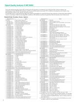
Due to the explosive growth of data traffic resulting from the popularity of smartphones and mobile terminals, network interfaces are transitioning to faster 200/400 GbE standards, and PCI bus interface speeds now exceed 10G. In addition, the equipment and chipsets using these interfaces support multi-channels and multi-protocols. The MP1900A series is a high-performance BERT with excellent expandability for supporting Physical layer evaluations of these high-speed interfaces. The all-in-one design is ideal for early stage R&D evaluations of all interfaces covering next-generation Ethernet...
Open the catalog to page 2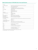
1: Removing and replacing the HDD by Customer is outside the scope of warranty coverage. *2: Operating voltage is -10% to +10% of rated voltage
Open the catalog to page 3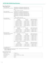
Bit Rate Setting Range (MU181000B synchronized operation) Bit Rate Setting Range (MU181500B synchronized operation) When the Output Clock Rate is set to Full Rate
Open the catalog to page 4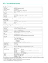
1: Since the output circuit is DC-terminated using the AC-coupled Bias Tee method, the same symbol pattern has a 50% change in output level over a continuous period of about 5 ps. *2: Configurable when 2ch Combination or 64G x 2ch Combination is set. *3: The MU195020A-z50 is required. This can be set only when Module Combination is set to Independent. If either Ch1 or Ch2 is set to Sequence, the other is also set to Sequence. *4: Requires both MU195020A-050/350 and MU195020A-051/351 options.
Open the catalog to page 5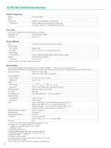
Pattern Sequence 1: Option x11 or Option x21 is installed and that Emphasis is not set. *2: If Option x01 is not available, then this is at 21 Gbit/s. If Option x01 is available, then this is at 32.1 Gbit/s. Amplitude: 1.0 Vp-p *3: When the value is set to 0. *4: Using oscilloscope with residual jitter of less than 200 fs rms. *5: Using oscilloscope with residual jitter of less than 70 fs rms. *6: Defined by PRBS 215 - 1, BER 10-12. *7: Cable error is not included. *8: Includes standard accessory Coaxial Adapter J1359A (K-P.K-J to SMA). *9: When Option x20 is available. *10: The output...
Open the catalog to page 6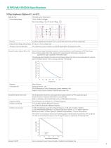
Emphasis Tap Cursor Setting Range Accuracy Emphasis Peak Voltage Setting Range Transition Time from Idle State Channel Emulator (Option 040 or 041) ±1 dB (typ., Defined for the preset of 8, 16, and 25 Gbit/s for PCIe 3 and PCIe 4 respectively) 0.1 Vp-p to 1.5 Vp-p (Single-end) <8 ns (Maximum time to transition to valid diff signaling after leaving Electrical Idle) Normal: Outputs signal emulating transmission channel equivalent to read S-parameter at PPG Data Output Inverse: Outputs signal with set De-Emphasis for compensating for transmission channel loss equivalent to read S-parameter at...
Open the catalog to page 7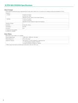
These values are monitored using an applicable part (Coaxial Cable J1439A, 0.8 m, K connector) at a sampling oscilloscope bandwidth of 70 GHz. *: When using an item with an oscilloscope residual jitter of less than 200 fs rms.
Open the catalog to page 8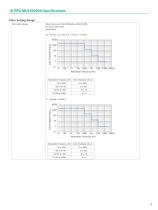
Jitter Setting Range When linking with MU181000A/B and MU181500B SJ1 Clock Output Rate At Half Rate 30 < Bit rate < 32.1 Gbit/s, 8 < Bit rate < 17 Gbit/s 10000 1000 p|B phbbii PiiiiP i PiiPili i
Open the catalog to page 9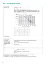
Jitter Tolerance Mask* Bit rate: 16, 28.1*, 32.1 Gbit/s* Pattern: PRBS 231 - 1 SSC with a 5300 ppm amplitude and RJ of 0.3 UI can be simultaneously applied by using MU181500B. These specifications are defined assuming the following conditions: Loopback connection to the MU195040A, defined by one specific temperature in the range of 20°C to 30°C. When RJ + BUJ is bigger than 0.5 UIp-p or SJ + RJ + BUJ is bigger than the standard value + 0.3 UIp-p, "Overload" is displayed on the MU181500B screen. The maximum applied modulation jitter depends on the bit rate. Refer to the jitter setting range...
Open the catalog to page 10
SI PPG MU195020A Specifications Extension Function PAM4 Supports the following by combining MU195020A with MZ1834A/B and G0375A. PAM4 signal generation • Amplitude (Single-end) 0.048 to 0.310 Vp-p (MZ1834A) • Amplitude (Single-end) 0.048 to 0.489 Vp-p (MZ1834B) • Amplitude (Single-end) 0.3 to 1.95 Vp-p (G0375A) PAM4 Emphasis signal generation (when Option x11 or Option x21 is installed) • Emphasis Peak Voltage (Single-end) 0.048 to 0.357 Vp-p (MZ1834A) • Emphasis Peak Voltage (Single-end) 0.048 to 0.564 Vp-p (MZ1834B) • Emphasis Peak Voltage (Single-end) 0.3 to 2.25 Vp-p (G0
Open the catalog to page 11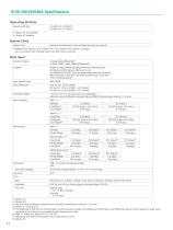
2.4 Gbit/s to 21.0 Gbit/s 2.4 Gbit/s to 32.1 Gbit/s *1: Option x01 not available *2: Option x01 available System Clock External, Clock Recovery, Clock and Data Recovery are optional1 *: Available when Option x22 is installed. If it is not installed, only External is available. Clock is recovered from the data input to the Data1 Input connector. *3: Absolute value of difference between Data and Data Threshold values shall be 1.5 V or less. *4: Option x11 or Option x21 *5: The Amplitude at NRZ input is the Auto Adjust function operation range. The Amplitude at PAM4 input is the PAM4 Auto...
Open the catalog to page 12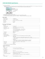
*9: Sensitivity of eye height. Eye height is the minimum value that induces no bit error when MU195040A receives the output signal from MU195020A + ATT in the measurement system shown in the following figure (using a sampling oscilloscope of 70 GHz band or higher for measuring output amplitude) Data Output Data Input ATT Eye Height Amplitude *10: When using 0.5 Vp-p Input and External Clock. *11: At PRBS15, Single-end, Mark Ratio 1/2 equivalent, and CTLE OFF, with MU195020A + G0375A *12: At Emphasis ON (best value within range of 1Pre < 3 dB/1Post < 1 dB) based on IEEE802.3bs measurement...
Open the catalog to page 13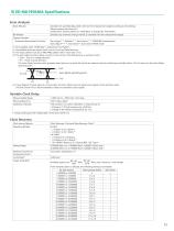
Error Analysis Block Window *1: Not available when "HSSB Data" is selected for Test Pattern. *2: Unavailable when the system clock is set to Clock and Data Recovery. *3: The input pattern must be an NRZ PRBS pattern with a mark ratio of 1/2. *4: The Auto Adjust function obtains a point in the vicinity of the following as an optimum point: • (Voh + Vol)/2 in voltage direction • (P1 + P2)/2 in phase direction The Auto Adjust function works properly when there are no mask-hits which are observed by the oscilloscope vertically within ±25 mV area from the Auto Adjust operating point. ■— Voh —...
Open the catalog to page 15All Anritsu catalogs and technical brochures
-
Electronic measuring instruments
24 Pages
-
MW90010A Coherent OTDR
8 Pages
-
OTA Product Catalog
20 Pages
-
BERTWave™MP2100B
24 Pages
-
Network Master™ Series
36 Pages
-
PIM Master™ MW82119B
2 Pages
-
MT8821C
20 Pages
-
PIM over CPRI Measurement
2 Pages
-
C-RAN Solutions
8 Pages
-
Site Master™ S331P
19 Pages
-
MG3710A Vector Signal Generator
36 Pages
-
Spectrum Master MS2712E/13E
32 Pages
-
MG3740A Analog Signal Generator
24 Pages
-
MD8475A Signalling Tester
28 Pages
-
Spectrum Master MS2720T
24 Pages
-
LMR Master S412E
2 Pages
-
VNA Master MS20xxB
16 Pages
-
Site Master S3xxE
20 Pages
-
VectorStar MS4640B Series VNA
32 Pages
-
PIM Master MW82119A
8 Pages
Archived catalogs
-
BTS Master MT8220T_2019
40 Pages
-
BTS Master MT8220T_2013
28 Pages
-
MD8430A Product Introduction
24 Pages
-
Signalling Tester
2 Pages
-
Optical Devices Product Guide
10 Pages
-
Analyzers catalogue
655 Pages


