Catalog excerpts

Technical Data Sheet ShockLine™ Modular 2-Port PhaseLync™ VNA ME7868A 1 MHz to 43.5 GHz 2 Meters to 25+ Meter
Open the catalog to page 1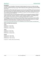
Technical Data Introduction The ME7868A is part of the ShockLine™ family of Vector Network Analyzers from Anritsu. It is a modular 2-port VNA consisting of two ShockLine MS46131A 1-port VNAs synchronized with PhaseLync™ technology. The ShockLine ME7868A 2-port VNA is available in three frequency ranges: 1 MHz to 8/20/43.5 GHz, and is capable of S-parameter and time domain measurements. The two ShockLine MS46131A VNAs determine the instrument performance of the ME7868A as they become the test ports and provide the source and measurement capabilities for the 2-port VNA. The MS46131A is based...
Open the catalog to page 2
Table of Contents Definitions. . . . . . . . . . . . . . . . . . . . . . . . . . . . . . . . . . . . . . . . . . . . . . . . . . . . . . . . . . . . . . . . . . . . . . . . . . . . . . . . . . . . . 4 System Dynamic Range . . . . . . . . . . . . . . . . . . . . . . . . . . . . . . . . . . . . . . . . . . . . . . . . . . . . . . . . . . . . . . . . . . . . . . . . . 5 High Level Noise — 1-Port MS46131A-010 . . . . . . . . . . . . . . . . . . . . . . . . . . . . . . . . . . . . . . . . . . . . . . . . . . . . . . . . . 5 High Level Noise — 1-Port MS46131A-020/043 . . . . . . . . . . . . . . ....
Open the catalog to page 3
ShockLine™ Definitions Warm-Up Time Temperature Range Error-Corrected Specifications Frequency Bands in Tables User Cables Discrete Spurious Responses Internal Reference Signal Interpolation Mode Typical Performance Characteristic Performance Transmission Performance Recommended Calibration Cycle Instrument Grounding Specifications Subject to Change Specifications All specifications and characteristics apply under the following conditions, unless otherwise stated. ME7868A 2-port VNAs consist of: • Two MS46131A, Base model, revision 2 • MS46131A-012, PhaseLync synchronization option,...
Open the catalog to page 4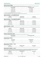
Specifications ShockLine™ System Dynamic Range System dynamic range for an ME7868A, consisting of two MS46131A VNAs with a PhaseLync option, is calculated as the difference between High source power and the noise floor (RMS) at the specified reference plane at 10 Hz IF Bandwidth. High isolation mode is used.
Open the catalog to page 5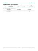
ShockLine™ Specifications Frequency Resolution, Accuracy, and Stability
Open the catalog to page 6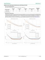
Specifications ShockLine™ Error-Corrected Specifications With calibration using TOSLN50A-8 or TOSLNF50A-8 N type connector calibration kits. Measurement Uncertainties The graphs give measurement uncertainties after the above error-corrected calibration. The errors are a worst-case contribution of residual directivity, load and source match, frequency response and isolation, network analyzer dynamic accuracy, and connector repeatability. 10 Hz IF Bandwidth is used. For transmission uncertainties, it is assumed that S11 = S22 = 0. A nominal amount of time drift is included in the computation...
Open the catalog to page 7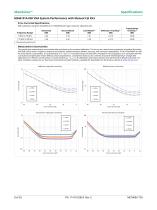
ShockLine™ Specifications Error-Corrected Specifications With calibration using the TOSLK50A-20 or TOSLKF50A-20 K type connector calibration kits. Measurement Uncertainties The graphs give measurement uncertainties after the above error-corrected calibration. The errors are a worst-case contribution of residual directivity, load and source match, frequency response and isolation, network analyzer dynamic accuracy, and connector repeatability. 10 Hz IF Bandwidth is used. For transmission uncertainties, it is assumed that S11 = S22 = 0. A nominal amount of time drift is included in the...
Open the catalog to page 8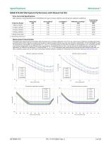
Specifications ShockLine™ Error-Corrected Specifications With calibration using TOSLK50A-43.5 or TOSLKF50A-43.5 K type connector calibration kits with generic calibration coefficients. Measurement Uncertainties The graphs give measurement uncertainties after the above error-corrected calibration. The errors are a worst-case contribution of residual directivity, load and source match, frequency response and isolation, network analyzer dynamic accuracy, and connector repeatability. 10 Hz IF Bandwidth is used. For transmission uncertainties, it is assumed that S11 = S22 = 0. A nominal amount...
Open the catalog to page 9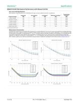
ShockLine™ Specifications Error-Corrected Specifications With calibration using TOSLK50A-43.5 or TOSLKF50A-43.5 K type connector calibration kits with .sip definitions. Measurement Uncertainties The graphs give measurement uncertainties after the above error-corrected calibration. The errors are a worst-case contribution of residual directivity, load and source match, frequency response and isolation, network analyzer dynamic accuracy, and connector repeatability. 10 Hz IF Bandwidth is used. For transmission uncertainties, it is assumed that S11 = S22 = 0. A nominal amount of time drift is...
Open the catalog to page 10
Specifications ShockLine™ Error-Corrected Specifications With calibration using the 2-port MN25208A SmartCal™ automatic calibration kit with connector options MN25208A-001, -002, -003 Measurement Uncertainties The graphs give measurement uncertainties after the above error-corrected calibration. The errors are a worst-case contribution of residual directivity, load and source match, frequency response and isolation, network analyzer dynamic accuracy, and connector repeatability. 10 Hz IF Bandwidth is used. For transmission uncertainties, it is assumed that S11 = S22 = 0. A nominal amount of...
Open the catalog to page 11
ShockLine™ Specifications Error-Corrected Specifications With calibration using the 4-port MN25408A SmartCal™ automatic calibration kit with connector options MN25408A-001, -002, -003 Measurement Uncertainties The graphs give measurement uncertainties after the above error-corrected calibration. The errors are a worst-case contribution of residual directivity, load and source match, frequency response and isolation, network analyzer dynamic accuracy, and connector repeatability. 10 Hz IF Bandwidth is used. For transmission uncertainties, it is assumed that S11 = S22 = 0. A nominal amount of...
Open the catalog to page 12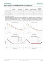
Specifications ShockLine™ Error-Corrected Specifications With calibration using the 2-port MN25218A SmartCal™ automatic calibration kit. Measurement Uncertainties The graphs give measurement uncertainties after the above error-corrected calibration. The errors are a worst-case contribution of residual directivity, load and source match, frequency response and isolation, network analyzer dynamic accuracy, and connector repeatability. 10 Hz IF Bandwidth is used. For transmission uncertainties, it is assumed that S11 = S22 = 0. A nominal amount of time drift is included in the computation as...
Open the catalog to page 13All Anritsu catalogs and technical brochures
-
Electronic measuring instruments
24 Pages
-
MW90010A Coherent OTDR
8 Pages
-
OTA Product Catalog
20 Pages
-
BERTWave™MP2100B
24 Pages
-
Network Master™ Series
36 Pages
-
PIM Master™ MW82119B
2 Pages
-
MT8821C
20 Pages
-
PIM over CPRI Measurement
2 Pages
-
C-RAN Solutions
8 Pages
-
Site Master™ S331P
19 Pages
-
MG3710A Vector Signal Generator
36 Pages
-
Spectrum Master MS2712E/13E
32 Pages
-
MG3740A Analog Signal Generator
24 Pages
-
MD8475A Signalling Tester
28 Pages
-
Spectrum Master MS2720T
24 Pages
-
LMR Master S412E
2 Pages
-
VNA Master MS20xxB
16 Pages
-
Site Master S3xxE
20 Pages
-
VectorStar MS4640B Series VNA
32 Pages
-
PIM Master MW82119A
8 Pages
Archived catalogs
-
BTS Master MT8220T_2019
40 Pages
-
BTS Master MT8220T_2013
28 Pages
-
MD8430A Product Introduction
24 Pages
-
Signalling Tester
2 Pages
-
Optical Devices Product Guide
10 Pages
-
Analyzers catalogue
655 Pages


