
- Catalogs
- Anlidar Industrial - MyTorq
- Torque Display User Manual


Torque Display User Manual
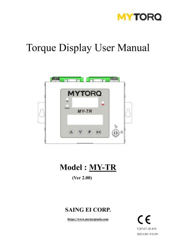
Torque Display User Manual
The device features a four-digit display for torque values and a 16x2 LCM for settings. Key functions include Up, Down, P (settings entry), and E/C (restore defaults/confirm actions). Status indicators include OK, NG, and OKALL.
Access the function menu by pressing 'P' for 3 seconds and entering a password. Key settings include program selection (1-99), batch count (1-250), time limit (0.00-9.99 sec), torque limit (0.0-550.00 KGF.cm), thread limit (0.0-999.9), slow start time, auto forward/reverse, and alarm signal time.
Describes connectors for external signals including start, reverse, disable, confirm, and clear functions. Output signals include start, brake, reverse, OK, NG, and OKALL.
Outlines confirmation methods using external sensors and manual inputs.
Describes error codes such as E3 for voltage-drop protection, indicating when the screwdriver stops due to voltage issues.
- Low-Voltage Protection: Activates when voltage is insufficient.
- Over-Temperature Protection (E4): Stops the screwdriver when internal temperature is too high.
- Rotation-Jamming Protection (E5): Stops the screwdriver if motor startup is abnormal.
- Direction Push Board Abnormality (E7): Stops the motor when direction is changed unexpectedly.
- Brake Signal Abnormality (E8): Stops the screwdriver if brake signal is abnormal.
- Communication Abnormalities (ES, ESC, EPC): Stops the screwdriver if communication signals are abnormal or if calibration is not done.
- OK: Displayed when fastening is complete.
- OKALL: Displayed when a batch is complete.
- NS: Error in operation, requires confirmation to proceed.
- NG: Various errors related to timing, torque, and turns.
- Dis: Displayed when certain functions are disabled.
- Hardware Connection: Connect barcode reader to MY-TR via RS232.
- Set Function Options: Configure serial interface and data frame settings.
- Operation Functions: Use barcode reader to switch programs, cancel AS and NS confirmations.
- Use only with MYTORQ components to avoid malfunctions and voiding guarantees.
- Do not modify connection ports without authorization.
- Handle cables carefully to avoid damage.
- Use exclusively with MYTORQ components.
- Stop operation if overheating or abnormal conditions occur.
- Ground all components to prevent electric shock.
- Controller sends data to external devices for synchronization and control.
- Barcode information is transmitted for control judgment or record saving.
- Shut off data is sent after each operation, requiring acknowledgment from external devices.
- Recommended software control flow includes cyclic communication and data feedback.
The document describes the MYTORQ MY-TR 2.0 Basic Data Output Protocol, focusing on communication between the device and external systems via RS232 port. It outlines various command formats and data structures used for communication.
- Communication Interface: RS232 with a 9-pin female connector.
- Baud Rate: 115200/9600 for MY-TR 1.7X.
- Data Format: ASCII.
- REQ0: Sends device status to the host every second after startup.
- REQ1: Sends barcode data to the host immediately after scanning.
- DATA0: Sends last shutoff data to the host immediately and repeats every second after screwdriver shutoff.
- CMD0: Host responds with system time to the device.
- REQ0 and DATA0 commands contain multiple fields separated by commas, with specific byte positions for each data type (e.g., year, month, date, etc.).
- CMD0 command includes fields for device name, date, time, checksum, and key code.
The document includes a detailed parts list for the MY-TR-V2.0 model, specifying part numbers, names, and quantities.
- Barcode Scanner and WIFI module connection methods are specified for MY-TR and MY-TR5 models.
Catalog excerpts
Torque Display User Manual SAING EI CORP. https://www.mytorqtools.com Y2F167-3E-019 20211201-V2129
Open the catalog to page 1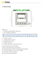
Display screen: 1. Four-digit seven-segment display of torque value 2. 16X2 LCM display setting function • C: Display count value • T: Display screwdriver action time • 999.9 display number of turns • Q: Display torque value Up Key: Setting mode Up key switch function. Down Key: Setting mode Down key switch function. P key: Press three seconds to enter/leave the setting mode/ Clear Sequence. E/C: Restore initial defaults/ Clear count value /CONFIRM. OK, NG, OKALL: Display status indicator. Key switch: Lock the key usage functions.
Open the catalog to page 2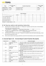
Action Limitation 3. Set function options and operating instructions 3-1. After the power is turned on, press the "E / C" button for 3 seconds to enter the menu of initial default, which must entry the password to enter. LOAD DEFAULT NO/DEFAULT Cancel/restore to factory setting The status “LC” is displayed on the 7-segment display when key lock has been used. After the power is turned on, press the "P" button for 3 seconds to enter the Function menu page, which must entry the password to enter. After enter the function menu page, parameter can be browsed and setting by press up and down button....
Open the catalog to page 6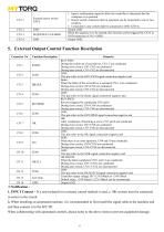
1. INPUT Contact » If a non-isolated (wet contact) control method is used, a 10K resistor must be connected in series on the circuit. 2. When installing an automated machine, it is recommended to first install the signal cable at the machine end and then connect it to the MY-TR. When collaborating with automated controls, please notes to the above items to prevent equipment damage.
Open the catalog to page 7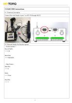
9. BARCODE instructions: 9-1. Hardware description Connect Bar code Reader to port 1 on MY-TR through RS232 9-2. Barcode Reader Set function options <Serial interface> Record Suffix ===>CR Baud Rate ===>9600 BPS <Data Frame> Data Bits ===>8 Parity ===>None Stop Bits ===
Open the catalog to page 9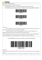
9-3. Operation function description 9-3.1. Set fasten program command on MY-TR first The program that can be used to switch the fasten program through Barcode Reader Use MYTORQ barcode for Program switching, 1-99 groups can be switched (CMD.P01-CMD.P99) Instructions: 99 sets of programs have been preset on the MY-TR. The barcode of the group to be used must be pasted on the workpiece in advance. (eg: CMD.P01~CMD.P99) When the workpiece comes in for fastening purpose, you need to scan the workpiece or preprepared barcode before the tool can be used and switch to the correct group. 9-3.2. Barcode...
Open the catalog to page 10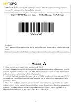
9-3.3. Barcode Reader cancels the NS confirmation command. When the workpiece fastening condition is wrong and NS is set, you can use Barcode Reader to release it. Use MYTORQ bar code format : CMD.C02 release NS (Nok Stop) Description: The NS function has been enabled on the MY-TR. When an NS occurs, the screwdriver locks out and cannot be used. The operator can use Barcode Reader to scan the prepared command bar code to release it for easy operation. Warning 1、Please use entire set of special electric screwdriver with MY-TR 2、The MY-TR should be used with MYTORQ’s power supply, electric screwdriver...
Open the catalog to page 11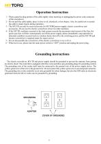
Operation Instruction 1、Please grasp the plug portion of the cable tightly when inserting or unplugging the power code connector of the screwdriver. 2、Do not pull the cable tightly, place it close to oil, chemicals, or hot objects. Also, be careful not to scratch the cable to sharp objects during operation. 3、The MY-TR can only be used exclusively for MYTORQ power supply, electric screwdriver and accessories. Do not use the electric screwdriver driver for other machines. 4、If the MY-TR overheats occurred or the load current exceeds the maximum rated current of the fuse, the quick type fuse will...
Open the catalog to page 12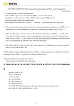
MY-TR V2.0/MY-TR5 Data transmission description and flow control suggestion VER:2020060201 {CMD0,0,0,0,0,0,0,YEAR,MONTH,DAY,HOUR,MINUTE,SECOND,0000,000 0} str8 0001~9999 YEAR str9 01~12 MONTH str10 01~31 DAY str11 00~23 HOUR str12 00~59 MINUTE str13 00~59 SECOND str14 0000-9999 Check Sum(year, month, day, hour, minute, and second plus sum) str15 0000-9999 Key Code(Check Sum + 5438)
Open the catalog to page 13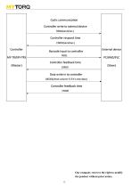
Cyclic communication Controller write to external device REQ0(send/sec.) Controller respond time CMD0(send/sec.) Barcode input to controller REQ1 External device PC/AMS/PLC Controller feedback time CMD0 Data write in to controller DATA0(check column 6 if it’s new data) Controller feedback time CMD0 Our company reserves the right to modify the product without prior notice. 13
Open the catalog to page 14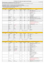
COMPORT Setting:Baud rate : 115200/9600(MY-TR 1.7X), Data bit : 8 , Stop bit : 1, Parity bit :NON
Open the catalog to page 15
Parameter Header+CMD Device Name Value Data Type String String Length 5 Byte Header+Command code Device Name(0: AMS, 1: DAS) Description Key Code+Tail ASCII code LF Communication interface : Connection RS232 : 1.Item 1 to 15 are separated by "," (ASCII 0x2c) 2.Reply to CMD0 when the time is inconsistent or repeat {DATA0} urn 2.WIFI module Connection method:MY-TR PORT2 Remark MWhen the trip information (DATA0) is continuously transmitted, it can be judged by the field six 0
Open the catalog to page 16
PARTS NAME-E PARTS NAME-C 機板成品 電流偵測扭力顯示 Terminal Cover Rubber Shim Srew-Power Controller Grounding Means 螺絲-電源接地線用
Open the catalog to page 18All Anlidar Industrial - MyTorq catalogs and technical brochures
 BSP-C32HL
16 Pages
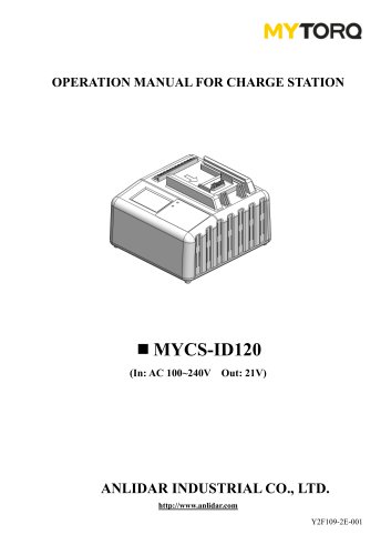 MYCS-ID120
10 Pages
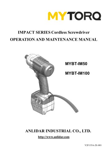 MYBT-IM50 MYBT-IM100
10 Pages
 OPERATION AND MAINTENANCE MANUAL
14 Pages
 MYP40-500N
7 Pages
 MYP40-500
10 Pages
 MYP32-300
8 Pages
 MYP32-60
8 Pages
 OPERATION AND MAINTENANCE MANUAL
11 Pages
 OPERATION AND MAINTENANCE MANUAL
10 Pages
 MY-SAVER User Manual
21 Pages
 MY-SIRIUS User Manual
49 Pages
 MY-EVO-mini User Manual
29 Pages
 Smart tools
8 Pages

Archived catalogs
 ACCESSORIES
2 Pages
 Power Shark
18 Pages
 MYTORQ High Torque
35 Pages
 MYTORQ Low Torque
32 Pages

- Electrical cable
- Feeder
- Battery charger
- Impact wrench
- Lithium battery
- 12 V battery
- Brushless electric screwdriver
- Corded electric screwdriver
- Straight electric screwdriver
- Automated feeder
- CE battery
- Pistol impact wrench
- Signal conditioner
- Charging post
- DC electric screwdriver
- Lithium battery charger
- Torque meter
- Pistol electric screwdriver
- Cordless electric screwdriver