
- Catalogs
- Anlidar Industrial - MyTorq
- MY-EVO-mini User Manual


MY-EVO-mini User Manual

MY-EVO-mini User Manual
The MY-EVO-mini model comes with accessories including a USB, tripod, manual, and warranty certificate. It operates on an AC voltage of 115V/230V with a frequency of 50-60Hz, and has a DC import voltage of 40V with an export power of 360W. The device weighs 3467g and is compatible with various screwdriver models.
The device features a panel with tool connection seats, communication ports, and power sockets, along with LED indicators for operational status and data ports.
The dashboard allows login with a default guest account, providing access to functions such as operation, job editing, data management, and settings. The homepage displays fastening information, tool status, and system messages.
Fastening Results: Displays operational status, job details, torque values, and fastening results with charts and modbus data.
Job Edit: Allows management of jobs, including adding, editing, copying, and deleting.
Data Management: Includes history data, logging information, and configuration settings.
Settings: Covers controller, tool, system, barcode, network, and update settings.
Information: Provides tool and controller information and manual downloads.
Users can manage job sequences and steps, setting parameters like screw count, timeout, and torque thresholds, with support for custom reverse modes and angle calculations.
Includes descriptions of external export and import controls, display status codes, and modbus instructions for advanced configuration and troubleshooting.
Includes target torque, hi/lo torque limits, monitoring torque by window, and upper/lower angle settings.
Features interrupt alarm and over angle stop functions.
Allows setting tightening direction and rotation speed.
Includes threshold mode and downshift mode settings.
Allows job selection and event editing, and configures output settings for job completion signals.
Displays history data and export options in CSV or ZIP format.
Includes controller settings and tool settings configurations.
Covers system settings and barcode management configurations.
Allows switching between processes by scanning barcodes, with job/process selection corresponding to scanned barcodes.
Supports dynamic and static wired network modes with configurable IP settings.
Updates can be performed via FTP or USB, displaying current firmware versions.
Displays tool and controller information, including serial numbers and firmware versions.
Configurable charts for displaying parameters like torque and rotation speed over time.
Supports external input and output control functions with custom signal definitions.
Lists error codes for various abnormal messages.
Uses MODBUS TCP/RTU protocols for communication with configurable settings.
The company reserves the right to modify the product without prior notice.
Catalog excerpts

MY-EVO-mini User Manual Model: MY-EVO-mini SAING EI CORP. https://www.mytorqtools.com
Open the catalog to page 1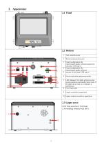
2.2 Bottom 1 Tool connection seat 2 Wired communication port 3 Export/configuration file export/import/update software/scanner for lock data, USB type-A 4 Export/configuration file export/import/update software/ 5 scanner for lock data, USB type A 6 Power cord socket and power switch 7 LED Indicator: The lights will turn on for normal operation and standby/sleep mode. If the lights do not turn on, it indicates a malfunction. 8 Prcol export port 9 Export screwdriver signal port 10 Import control screwdriver signal port 2.3 Upper cover 1.DC fuse seat (incl. 15A fuse) 2. Grounding terminal seat...
Open the catalog to page 4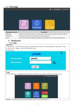
Homepage Functions
Open the catalog to page 5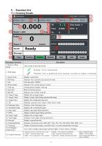
5-1. Fastening Results Homepage Functions
Open the catalog to page 6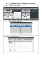
5-1-1. Charts & Modbus / Retrieval / Information Page Introduction 5-1-1. Charts & Modbus / Retrieval / Information Page Introduction Switch to view Charts / Modbus. |D Operation Total Seq 1/1 Seq Clear Step ID 1 Cau ISeq Name SEQ-1 Total Seq 1/1 Seq Clear Step ID ll 2. Call Compensated Target Torque: Enter the actual torque value to automatically calculate and populate the STEP compensation. (!) Operation_ 3. Information Fastening Step Parameter List (!) Operation
Open the catalog to page 7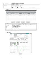
5-2-3. Step New Step | Tbrqu^T^n^e" jwiunHiyinq 'argue t>y Window Upper(N>) 30 lower(% 30 Interrupt AJarm Over Angle Stop Direction Doinyif.ee i Joint OffsetIN m) # Plus Angle Threshold(deg) Downturn TorquclN.ml Oownshllt Speed(rpm)
Open the catalog to page 11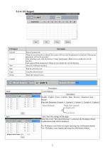
Event Options Disable / Enable / Clear / Confirm / Start / Reverse / Sequence Clear / One-time Detection /Custom 1 / Custom 2 / Custom 3 / Custom 4 / Custom 5 Signal Selection Blank (Not selected) High Level Save: Save the settings on this page. When the event "One-time Detection" is selected, the Workpiece Reset Confirmation field will be displayed. No: Workpiece reset does not require pressing the confirmation button. Yes: Workpiece reset requires pressing the confirmation button.
Open the catalog to page 13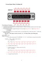
1. First Input (IN_1): Short-circuit (ON) — enter binary job switching mode. (Note 1) 2. Convert the target Job ID number into 8-bit binary (decimal — binary). If the binary number has fewer than 8 digits, add leading zeros. (Note 2) 3. The converted 8-bit Job ID is mapped from high to low bit onto Input Group 5 (IN_5) — Input Group 12 (IN_12). 4. After confirming that all 8 bits are entered correctly, use Second Input (IN_2): Short-circuit (ON) — confirm and Operation switching. Note 1:IN_1 = OFF (Open): Normal event mode. IN_1 = ON (Short): Binary job switching mode. 28 = 256, Binary representation:...
Open the catalog to page 14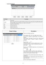
Output Settings Select Event, Signal, and Time. Event Options: OK / NG / Over Upper Limit / Under Lower Limit / Sequence Complete Signal / Job Complete Output / Motor Signal / Start Signal / Reverse Screw / Barcode Stop / Barcode / Custom 1 / Custom 2 / Custom 3 / Custom 4 / Custom 5 Signal Modes : ___ Continuous Output: I lie indicator light remains on when the screwdriver stops. It turns off when the screwdriver starts again. _r^ Single Cycle: The indicator light stays on for a duration set by the timer. Start Output: After the screwdriver stops, releasing the activation switch (press plate,...
Open the catalog to page 15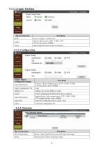
5-3-3. Graphic File Data Disk Storage Space Storage Usage: Displays the current disk usage percentage. Fastening Data: Deletes fastening records.
Open the catalog to page 17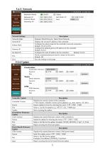
Network Settings
Open the catalog to page 23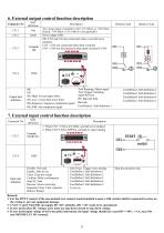
The voltage output of controller is DC+12V/100mA or +24V/50mA. Default: +24V/50mA (+12V/100mA is also applicable) OK: CN3 and CN4 are connected when a screwdriver is initiated. CN3 + CN4 are connected when short-circuited Output state definition NG-High: Exceed upper limit. NG-Low: Lower than lower limit. OK-Sequence: Sequence completion signal OK-JOB: Job completion signal Tool Running: Motor signal Tool Trigger: Initiating signal Reverse BS: Barcode Stop Barcode 7. External input control function description Connector No Input state definition Disable: Not used Enable: Able to use Clear: Clear...
Open the catalog to page 26
Modbus Data Transmission Read/ Write Commands into fields Read Holding Register: 0x03, Write Single Register: 0x06 Write Multiple Registers: 0x10 Controller (Slave) Reply command into fields External device PC/PLC (Master) Communication method uses MODBUS TCP/ MODBUS RTU standard protocol. Connection methods are: • TCP connection and setup: 1. Selecting LAN-DHCP or LAN-STATIC from controller. 2. Configuring the controller's IP to be on the same domain as the PC's. (Find out an IP from LAN-DHCP or select/ setup an IP address from STSTIC IP or GATEWAY IP.) 3. Setting the Server port (default is...
Open the catalog to page 28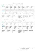
Our company reserves the right to modify the product without prior notice.
Open the catalog to page 29All Anlidar Industrial - MyTorq catalogs and technical brochures
 BSP-C32HL
16 Pages
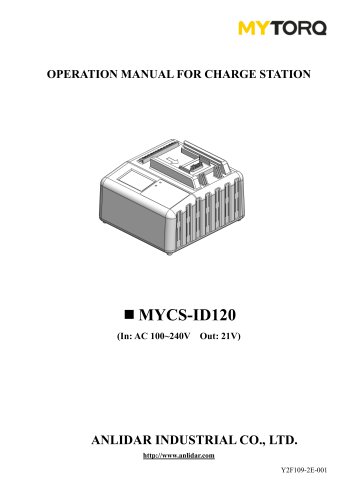 MYCS-ID120
10 Pages
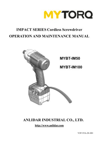 MYBT-IM50 MYBT-IM100
10 Pages
 OPERATION AND MAINTENANCE MANUAL
14 Pages
 MYP40-500N
7 Pages
 MYP40-500
10 Pages
 MYP32-300
8 Pages
 MYP32-60
8 Pages
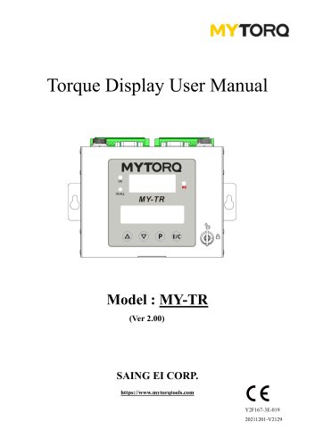 Torque Display User Manual
18 Pages
 OPERATION AND MAINTENANCE MANUAL
11 Pages
 OPERATION AND MAINTENANCE MANUAL
10 Pages
 MY-SAVER User Manual
21 Pages
 MY-SIRIUS User Manual
49 Pages
 Smart tools
8 Pages



Archived catalogs
 ACCESSORIES
2 Pages
 Power Shark
18 Pages
 MYTORQ High Torque
35 Pages
 MYTORQ Low Torque
32 Pages

- Electrical cable
- Feeder
- Battery charger
- Electric screwdriver
- Impact wrench
- Lithium battery
- 12 V battery
- Brushless electric screwdriver
- Corded electric screwdriver
- Straight electric screwdriver
- Automated feeder
- CE battery
- Pistol impact wrench
- Signal conditioner
- Charging post
- DC electric screwdriver
- Lithium battery charger
- Torque meter
- Pistol electric screwdriver
- Cordless electric screwdriver