- Company
- Products
- Catalogs
- News & Trends
- Exhibitions
PPCP3-M1
1 /10Pages

PPCP3-M1
1 /10Pages
Catalog excerpts

• MEMS Silicon Capacitive Pressure Sensor • Differential / Gauge Operation • Pressure Range : 10, 50, 100, 200, 400, 500, 750, 1000 mbar • RoHS Compliant • High Resolution • Low Power Consumption • Standard 8-pin DIP package Description Pewatron has developed a series of pressure sensors targeting a variety of markets. The PPCP3-M1 is a MEMS based silicon capacitive pressure sensor with world class reso-lution. The pressure sensor is underpinned by ESS's innovative SOI-surfacemicromachining technology. PPCP3-M1 is a differential pressure sensor with a resolution of <15pbar with SPI and I2Ctm interfaces. The sensor includes a high resolution XA ADC to digitize the signal. The digital output is ful-ly calibrated and temperature compensated based on the internal temperature sensor and the factory calibration coefficients which are stored in the embedded memory. Thus the sensor is ready to be installed directly to the end user system without further processing. A low phase noise oscillator is also integrated, eliminating the need for any external components. Different power modes are available enabling low power operation, while the output rate, thus the conversion speed is programmed allowing the end user to customize /optimize performance. Parameters of the sensor can be programmed on the fly on every power on reset. The sensor provides high accuracy 32- bit pressure and temperature outputs. PPCP3-M1 sensor is a Silicon Capacitive Pressure Sensor with excellent long term stability. The sensor is incorporated in a standard 8-pin DIP package with a variety of pneumatic port options. • Differential / Gauge operation • High accuracy [0.5%FS including repeatability, hysteresis and thermal effects] • High sensitivity / Resolution • Excellent thermal behavior • Standard Footprint • Different Power Modes • No external Components Needed • Overpressure at high side at least 4 bar independent of sensor pressure range Target Application Areas • Medical • Consumer goods • HVAC • Filtration Systems • Process Automation • Gas Flow • Flow Switch Competitive sensor & power supply solutions worldwide
Open the catalog to page 1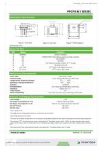
High Side Port Figure 1: Side View Performance Characteristics DO NOT CONNECT POWER SUPPLY (Decoupling capacitor already included) NO CONNECT GROUND CHIP SELECT (Connect to VDD if I2CTM is used) SPI SERIAL DATA IN I2CTM DATA / SPI SERIAL DATA OUT I2CTM CLOCK / SPI CLOCK Sensor Type Pressure Range Compensation Temperature Range Operating / Storage Temperature Accuracy Humidity Effects Interfaces Proof Pressure Media Compatibility < ±0.5% FS2 No change up to 90%RH Non condensing Digital: SPI / I2CTM x 43 Inert, Non-Corrosive, Non-Condensing, Clean Gases Max Power Consumption @ +3.3V 3.8mA (Continuous...
Open the catalog to page 2
PPCP3-M1 provides a 32-bit, 2's complement, fixed-point digital output which corresponds to the calibrated and temperature compensated data. The calibrated data are calculated by the calibration and temperature compensation logic unit, after the programming of the proper calibration coefficients (Factory Programmed). The calibrated data can be read through the Calibrated Data Registers shown in Table 1. The 4 registers which compose the 32-bit calibrated data should be read by using a multiple read transaction of 4 bytes in order to assure that the 4 bytes read correspond to the same data sample....
Open the catalog to page 3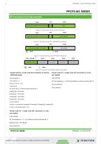
SPI Transaction and Code Examples 7 Bits 1 Bit 8 Bits Figure 5: General Format of an SPI Transaction 7 Bits 1 Bit 8 Bits Figure 6: General Format of an SPI WRITE Transaction 7 Bits 1 Bit 8 Bits MOSI MISO Figure 7: General Format of an SPI READ Transaction 7 Bits + R/W Bit '1 ' 8 Bits 8 Bits 8 Bits 8 Bits ^TDDRESStoREA^J^ATABYTE^J^ATABYTE^J^ATABYTE^J^ATABYTE^ ^ MOSI | MISO Figure 8: Format of an SPI MULTI-READ Transaction Pseudo Code for a multi read SPI transaction to read the Pseudo Code for a single write SPI transaction to write calibrated...
Open the catalog to page 4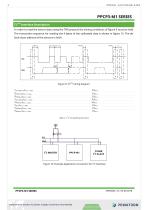
PPCP3-M1 SERIES I2CTM Interface Description In order to read the sensor data using the TWI protocol the timing conditions of figure 9 must be held. The transaction sequence for reading the 4 bytes of the calibrated data is shown in figure 15. The default slave address of the sensors is 0x5A ThSTART TSCL_HIGH TSCL_LOW Figure 9: I2CTM timing diagram TSCL_HIGH ThSTART @ fMCLK = 1.2MHz ThDATA @ fMCLK = 1.2MHz TSCL_LOW @ fMCLK = 1.2MHz TsSTOP @ fMCLK = 1.2MHz TPS @ fMCLK = 1.2MHz TsSTART @ fMCLK = 1.2MHz TsDATA @ fMCLK = 1.2MHz Table 2: I2C Timing Requirements VDD Figure 10: Example Application Connection...
Open the catalog to page 5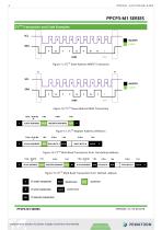
PPCP3-M1 SERIES I2CTM Transaction and Code Examples S MASTER SLAVE Figure 11: I2CTM Slave Address WRITE Transaction S MASTER SLAVE Figure 12: I2CTM Slave Address READ Transaction 7 Bits + R/W Bit 0 SLAVE ADDRESS REGISTER ADDRESS Figure 13: I2CTM Register Address Definition 1 Bit SLAVE ADDRESS Figure 14: I2CTM Multi Read Transaction from last defined address 7 Bits + R/W Bit 0 SLAVE ADDRESS REGISTER ADDRESS SLAVE ADDRESS Figure 15: I2CTM Multi Read Transaction from defined address S MASTER NACK
Open the catalog to page 6
Pseudo Code for a multi read I2C transaction to read the calibrated output int8 DataByte[4]; int32 CalData = 0; Float32 Pressure = 0.0; I2C_Start(); Ack = I2C_Write (0x5A << 1 | 0x01); PPCP3-M1 SERIES Pseudo Code for a single write I2C transaction to write one register I2C_Start(); Ack = I2C_Write (0x5A << 1 | 0x01); If (Ack == 0) { Ack = I2C_Write(Register Address); If (Ack == 0) { Ack = I2C_Write(0x00); If (Ack == 0) { I2C_Start(); //Restart Condition Ack = I2C_Write(0x5A << 1 & 0xFE); If (Ack == 0) { DataByte[0] = I2C_Read(ACK); DataByte[1] = I2C_Read(ACK); DataByte[2] = I2C_Read(ACK); DataByte[3]...
Open the catalog to page 7
For the calibration and temperature compensation of the pressure sensor taking into account the pressure range, the temperature compensation range, Pewatron is configuring the ASIC with the necessary parameters to reach the optimum performance in terms of accuracy. These configuration settings are factory programmed on the OTP memory. These settings can be altered during run time by accessing the corresponding configuration register but will revert to the factory settings once the sensor is pow-er cycled and power on reset takes effect. Depending on the given transaction types and combination...
Open the catalog to page 8All Angst+Pfister Sensors and Power AG catalogs and technical brochures
 SQ-UST_L_0105-01
4 Pages
 SQ-UST_L_0104-01
4 Pages
 SQ-UST_L_0103-01
4 Pages
 SQ-UST_L_0003-01
3 Pages
 SQ-UST_L_0002-01
3 Pages
 SQ-UST_L_0001-01
3 Pages
 PFLOW Series
5 Pages
 Model PFLOW3000 Series
16 Pages
 LoadSensor StarterKit
3 Pages
 Model PFLOW2001 Series
14 Pages
 PSB82_1685-21629-0010-E-1118
3 Pages
 PHPS5600 Pressure Transducer
6 Pages
 PEWA200 Pressure Transmitter
7 Pages
 PZA-MC25-N/P
2 Pages
 PEWA100
9 Pages
 HLP-80H series
5 Pages
 HLP-40H series
5 Pages
 HBG-60P series
6 Pages
 UHP-750 series
6 Pages
 XLG-50 seri es
9 Pages
 DAP-04 series
8 Pages
 POB-30 series
11 Pages
 RHP-1U Rack System
9 Pages
 RFP-M8M4-5A
5 Pages
 RFP-M5M3-3A
4 Pages
 RFP-M2M3-3A
4 Pages
 RFP-M1M3-3A
4 Pages
 NCL CL1 01
4 Pages
 IRL RGB 01
4 Pages
 IRL CL2 01
4 Pages
 MSR385WD
3 Pages
 MSR145WD
3 Pages
 MSR 145
3 Pages
 M2029
M20293 Pages
 MSR165
3 Pages
 CRM102.1
33 Pages
 CRM200
39 Pages
 CRM100
37 Pages
 FPM
FPM4 Pages
 FGN
FGN4 Pages
 FPN
FPN4 Pages
 PBM220-A14N series
14 Pages
 PBM220 series
15 Pages
 PBM210-A20K Series
14 Pages
 STX Series – Model 13A
11 Pages
 CCD Series – Model 53A
7 Pages
 CCD Series – Model 54D
20 Pages
 APB2Series
5 Pages
 AP4Series
5 Pages
 AP2Series
5 Pages
 PHPS-7500 OEM
6 Pages
 AG4Series
6 Pages
 AG2Series
5 Pages
 New Pewatron brochure
11 Pages
 GST220A
4 Pages
 GSM40B
6 Pages
 GSM36B
4 Pages
 GSC25E
5 Pages
 TDR-480
5 Pages
 GC120
GC1204 Pages
 HDR-30
5 Pages
 GSM220A
6 Pages
 EPP-400
5 Pages
 ENP-120
5 Pages
 ENC-120
6 Pages
 ATX-100
4 Pages
 RPS-200
7 Pages
 APBR30X75
2 Pages
 APBR30X60
2 Pages
 APBR 30X50 MM
2 Pages
 PSB54/16
2 Pages
 PSB54/14
2 Pages
 PSB36T/16
2 Pages
 PSB35T/12
2 Pages
 PSB25T/16
2 Pages
 PSB25T/12
2 Pages
 PSB21/12
2 Pages
 PSB 21
2 Pages
 AD-Series
16 Pages
 DMU11
DMU113 Pages
 HDR-30 series
5 Pages
 DMU30-01
25 Pages
 DMU30
DMU303 Pages
 DKA30 serie s
2 Pages
 DCW12
DCW122 Pages
 DCW05
DCW052 Pages
 EH - EF 80 C/P/K
3 Pages
 7S Series
3 Pages
 Model CE36M
3 Pages
 EX 80 A
3 Pages
 STX13A-D_100-31-410-005-EH-0817
11 Pages
 PBM220_100-33-421-003-EH-1216
16 Pages
 ABS5_100-33-102-001-EH-1016
2 Pages
 PHPS-8500_100-31-331-003-EH-0617
12 Pages
 100 33 102 012 EH 0315
6 Pages
 100 33 102 007 EH 0315
5 Pages
 UFO
UFO3 Pages
 UFO-M2
3 Pages
 Dummy DC-Motoren
2 Pages
 FCX-MP1000-Extern-FH-CH
3 Pages
 GC30E
GC30E3 Pages
 RPS-400
11 Pages
 GC 330
4 Pages
 EL30
EL303 Pages
 EA PROFIBUS
7 Pages
 EAMW
EAMW3 Pages
 AAM58
AAM584 Pages
 EAM36
EAM363 Pages
 CARBONOXY25
2 Pages
 CARBONDIO-%
2 Pages
 FCX-ML25-EXTERN-CH
14 Pages
 FCX-MC25-CH
3 Pages
 FCX-MC05-CH
3 Pages
 FCX-TR0025
4 Pages
 LP-10HA
3 Pages
 FCX-UC-CH
9 Pages
 901.1-EX
5 Pages
 FC22
FC223 Pages
 MILLINEWTON
3 Pages
 PFLOW10U-2210
5 Pages
 901.1
901.15 Pages
 HX-EP
HX-EP6 Pages
 VQ548MP & MP-7217
5 Pages
 Air quality sensing
6 Pages
 Tailor-made
10 Pages
 RAZTEC
13 Pages
 The SGX-SureCO
3 Pages
 930 Climair
5 Pages
 984 pressure transmitter
5 Pages
 PEM pressure transmitter
5 Pages
 Pressure sensor CCD54
4 Pages
 MSP-600 600W AC/DC
5 Pages
 FCX-MP1000-Extern-FH-CH
3 Pages
 Pewatron_Flyer_EN
8 Pages


- Electromotor
- Challenge Power Transmission flow meter
- DC electromotor
- Synchronous motor
- Challenge Power Transmission liquid flow meter
- Force sensor
- Challenge Power Transmission gas analyzer
- Multipole motor
- Angular encoder
- Challenge Power Transmission concentration analyzer
- Challenge Power Transmission resistance temperature sensor
- Challenge Power Transmission pressure transmitter
- Tension/compression force transducer
- Electromotor for industrial applications
- Incremental encoder
- EC motor
- Challenge Power Transmission analog pressure transmitter
- 24 V motor
- Gas flow monitor